(Model 31-695) PART NO. 902122 (0112) Copyright © 2001 Delta Machinery To learn more about DELTA MACHINERY visit our website at: www.deltamachinery.com. For Parts, Service, Warranty or other Assistance, please call ESPAÑOL: PÁGINA 21 1-800-223-7278 (In Canada call 1-800-463-3582).
GENERAL SAFETY RULES Woodworking can be dangerous if safe and proper operating procedures are not followed. As with all machinery, there are certain hazards involved with the operation of the product. Using the machine with respect and caution will considerably lessen the possibility of personal injury. However, if normal safety precautions are overlooked or ignored, personal injury to the operator may result.
ADDITIONAL SAFETY RULES FOR BELT / DISC SANDERS WARNING: FAILURE TO FOLLOW THESE RULES MAY RESULT IN SERIOUS PERSONAL INJURY. 1. DO NOT operate your machine until it is completely assembled and installed according to the instructions. 18. AVOID awkward hand positions where a sudden slip could cause a hand to move into the sanding belt or disc. 2. IF YOU ARE NOT thoroughly familiar with the operation of abrasive finishing machines, obtain advice from your supervisor, instructor or other qualified person.
POWER CONNECTIONS A separate electrical circuit should be used for your machines. This circuit should not be less than #12 wire and should be protected with a 20 Amp time lag fuse. If an extension cord is used, use only 3-wire extension cords which have 3prong grounding type plugs and matching receptacle which will accept the machine’s plug.
EXTENSION CORDS Use proper extension cords. Make sure your extension cord is in good condition and is a 3-wire extension cord which has a 3-prong grounding type plug and matching receptacle which will accept the machine’s plug. When using an extension cord, be sure to use one heavy enough to carry the current of the machine. An undersized cord will cause a drop in line voltage, resulting in loss of power and overheating. Fig. D, shows the correct gauge to use depending on the cord length.
UNPACKING Your new Belt/Disc Sander and Stand is shipped complete in one container. Carefully unpack the sander, stand, and all loose items from the shipping container. Fig. 2, illustrates the sander and its component parts. Fig. 3, illustrates the component parts of the stand. 1. Sander with 6" x 48" Sanding Belt and Backstop 1 2. 9" Sanding Disc 3. Drive Belt 4. Sanding Disc Plate 5 5. Belt and Pulley Cover 4 14 6. Disc Cover 7. M4.2 x 13mm Panhead Screws (3) 9 6 8. Plug 10 9.
ASSEMBLY INSTRUCTIONS WARNING: FOR YOUR OWN SAFETY, DO NOT CONNECT THE SANDER TO THE POWER SOURCE UNTIL THE MACHINE IS COMPLETELY ASSEMBLED AND YOU READ AND UNDERSTAND THE ENTIRE OWNERS MANUAL. ASSEMBLING STAND IMPORTANT: ANY LETTER DESIGNATIONS THAT MAY BE STAMPED ON THE BRACES OF THE STAND ARE FOR PRODUCTION PURPOSES ONLY AND ARE NOT USED FOR ASSEMBLING THE STAND. TO ASSEMBLE THE STAND, PLEASE FOLLOW THE INSTRUCTIONS DESCRIBED BELOW. SIZES ARE GIVEN TO HELP IDENTIFY THE COMPONENTS OF THE STAND. 1.
ASSEMBLING BELT AND PULLEY GUARD Assemble belt and pulley guard (A) Fig. 8, to the machine using two M6 x 55mm hex socket head screws (B), M6.4 lockwashers and M6.4 flat washers as shown. NOTE: Make certain plug (C) is installed into guard. A B C ASSEMBLING SANDING DISC PLATE Fig. 8 C 1. Slide sanding disc plate (A) Fig. 9, onto drive shaft (B) making certain key (C) in drive shaft (B) fits into keyway (D) of disc plate (A). A D B 2. Slide sanding disc plate (A) Fig.
ASSEMBLING LOWER COVER FOR SANDING DISC Assemble lower cover (A) Fig. 13, to belt and pulley guard (B) using three M4.2 x 13mm pan head screws (C). B C NOTE: MAKE SURE SANDING DISC DOES NOT CONTACT COVER. IF CONTACT IS MADE, THE SANDING DISC MUST BE REPOSITIONED ON THE DISC PLATE. A Fig. 13 ASSEMBLING DISC SANDER TABLE B 1. Insert support rod (A) Fig. 14, into hole in side of sander until rod (A) extends approximately 5-1/2" out from the machine.
LOCKING SWITCH IN THE “OFF” POSITION IMPORTANT: When the machine is not in use, the switch should be locked in the “OFF” position to prevent unauthorized use. This can be done by grasping the switch toggle (B) and pulling it out of the switch, as shown in Fig. 20. With the switch toggle (B) removed, the switch will not operate. However, should the switch toggle be removed while the sander is running, it can be turned “OFF” once, but cannot be restarted without inserting the switch toggle (B). B Fig.
ADJUSTING SANDING ARM STOP A A positive stop is provided to position the sanding arm level with the workbench when the arm is in the horizontal position. 1. DISCONNECT MACHINE FROM POWER SOURCE. 2. Place the sanding arm as far as possible in the horizontal position. B C 3. Place a level (A) on the sanding belt and check to see if the arm is level, as shown in Fig. 24. Fig. 24 4. If an adjustment is necessary, loosen lock nut (B) Fig.
ADJUSTING TABLE SQUARE WITH SANDING DISC 1. DISCONNECT MACHINE FROM POWER SOURCE. C 2. Using a combination square (C) Fig. 28, place one end of the square on the table with the other end against the sanding disc as shown in Fig. 28, and check to see if the table is 90 degrees to the disc. 3. If the table surface is not 90 degrees to the disc, loosen table lock knob (A) Fig. 28, adjust table square with disc and tighten lock knob (A). B 4. Adjust pointer (B) Fig.
ACCESSORY MITER GAGE An accessory miter gage is available for your machine and is used with the disc table. The miter gage body (A) Fig. 32, can be tilted right or left for angle or miter sanding by loosening lock knob (B), and rotating miter gage body to the desired angle. Tighten lock knob (B). B A Fig. 32 A USING TABLE ASSEMBLY WITH SANDING BELT C When the sanding arm (A) Fig.
ADJUSTING DUST SHIELD If your sander is connected to a dust collection system, the sander is equipped with a manually operated dust shield (A) Fig. 36, which must be adjusted to suit the sanding operation. 1. If you are sanding with the disc, push in on dust shield (A) Fig. 36. A Fig. 36 2. If you are sanding on the belt, pull dust shield (A) Fig. 37, outward. A Fig. 37 WRENCH STORAGE A A hole is provided in the stand for storing the hex wrench (A) Fig. 38, supplied with the sander. Fig.
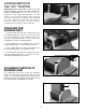
REPLACING SANDING BELT 1. DISCONNECT MACHINE FROM POWER SOURCE. B 2. Remove upper sanding drum guard. Loosen two screws (A) Fig. 40, and remove backstop (B). A 3. Loosen two screws (C) Fig. 40, and remove support bracket (D). Fig. 41 illustrates backstop and support bracket removed from the machine. D C Fig. 40 4. Slide tension lever (E) Fig. 42, to the right to release tension on sanding belt (F). Remove sanding belt (F) from both sanding drums. Fig. 41 F E 5.
REPLACING SANDING DISC When it becomes necessary to replace the sanding disc, proceed as follows: 1. DISCONNECT MACHINE FROM POWER SOURCE. 2. Loosen screw (A) Fig. 44, and remove table assembly (B). 3. Remove three screws (C) Fig. 45, and lower cover (D). 4. Peel off old disc (E) as shown in Fig. 46. 5. Make sure the disc plate (F) Fig. 46, is clean and peel backing from new sanding disc.
SANDING INSIDE CURVES Inside curves can be sanded on the top sanding drum, as shown in Fig. 49. NOTE: Replace sanding drum guard after sanding operation is completed! SANDING OUTSIDE CURVES Outside curves should be sanded on the sanding disc as shown in Fig. 50. WARNING: ALWAYS SAND ON THE LEFT (DOWNWARD) SIDE OF THE SANDING DISC, AS SHOWN. SANDING ON THE RIGHT (UPWARD) SIDE OF THE SANDING DISC COULD CAUSE THE WORKPIECE TO FLY UP, WHICH COULD BE HAZARDOUS. Fig.
ACCESSORIES A complete line of accessories is available from your Delta Supplier, Porter-Cable • Delta Factory Service Centers, and Delta Authorized Service Stations. Please visit our Web Site www.deltamachinery.com for a catalog or for the name of your nearest supplier. WARNING: Since accessories other than those offered by Delta have not been tested with this product, use of such accessories could be hazardous. For safest operation, only Delta recommended accessories should be used with this product.
NOTES 19
NOTES 20