
Instruction manual


8
ASSEMBLY
FOR YOUR OWN SAFETY, DO NOT CONNECT THE MACHINE TO THE POWER SOURCE UNTIL
THE MACHINE IS COMPLETELY ASSEMBLED AND YOU READ AND UNDERSTAND THE ENTIRE
INSTRUCTION MANUAL.
CASTER ASSEMBLY /
FOOT LEVER
1. DISCONNECT MACHINE FROM
POWER SOURCE.
2. Place the motor cabinet on its side.
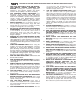
3. Align the three holes in the bracket (B) Fig. 2A, with
the three holes in the inside of the base (C).
4. Align the three holes in the pivot bracket (D) Fig. 2B,
with the three holes in the outside of the base (C).
5. Insert a 3/8-16x1" carriage head bolt through the
hole in bracket (B) Fig. 2A, the base (C), and the pivot
bracket (D) Fig. 2B. Place a 3/8" flat washer on the
screw, and thread a 3/8-16 hex nut on the screw and
tighten securely. Repeat this process for the two
remaining holes.
6. Align the two holes in the caster assembly (E) Fig.
2C, with the two holes (F) in the pivot bracket.
Fig. 2A
Fig. 2B
Fig. 2C
B
C
D
C
E
F