
Manual
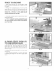
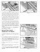
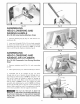
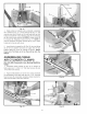
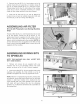
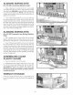

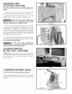
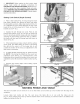

Fig.27
4. Makecertainaircyiinderrodis retractedcompbteiy
intocyiinder(E)Fig.27.Looseniocknut(K)Fig.27,and
unscrewhexendof cbvb rod(L)untiihobsiineupwith
hobsinbracket(N).Usingretainingchip(A)andretaining
pin(B),whichwereremovedinSTEP1,fastencbvis(L)
to bracket(N).Refightenbcknut(K)Fig.27.NOTE:It
maybenecessaryto ioosenscrews(R)Fig.28,inorder
to getpinto iineupwithcbvis.
5. Insertblackairsupplyline(S)Fig.28,intotopfitting
(G)of the air cylinderandblueair supplyline(V)into
bottomfitting(H)of the aircylinderas shown.NOTE:
Pushend of air minesas far as they will go into the
Fig. 28
ASSEMBLING TABLE
AIR CYLINDER CLAMPS
{For 32-326 Pneumatic Line Boring Machine
Only}
1. Assembb champ bracket (A) Fig. 29, to bottom of
table using two 1/4-20x1-1/4" flat head screws (B) and
1/4-20 hex lock nuts (C).
2. Figure 30 illustrates one of the two clamp brackets
(A) assembled to the table with the two 1-1/4" long fiat
head screws (B). Assemble remaining clamp bracket to
other end of table in the same manner.
Fig. 31
14
Fig. 29
Fig. 30
Fig. 32