(Model 32-325) 13-Spindle Pneumatic Line Boring Machine (Model 32-326) Model 32-325 Shown with Accessory 32-331 Stand Model 32-326 Shown with Accessory 32-331 Stand PART NO. 449-01-651-0005 - 11-03-03 Copyright © 2003 Delta Machinery To learn more about DELTA MACHINERY visit our website at: www.deltamachinery.com. For Parts, Service, Warranty or other Assistance, please call 1-800-223-7278 (In Canada call 1-800-463-3582).
SAFETY GUIDELINES - DEFINITIONS This manual contains information that is important for you to know and understand. This information relates to protecting YOUR SAFETY and PREVENTING EQUIPMENT PROBLEMS. To help you recognize this information, we use the symbols to the right. Please read the manual and pay attention to these sections. Indicates an imminently hazardous situation which, if not avoided, will result in death or serious injury.
FAILURE TO FOLLOW THESE RULES MAY RESULT IN SERIOUS PERSONAL INJURY. 12. USE THE RIGHT MACHINE. Don’t force a machine or an attachment to do a job for which it was not designed. Damage to the machine and/or injury may result. 13. USE RECOMMENDED ACCESSORIES. The use of accessories and attachments not recommended by Delta may cause damage to the machine or injury to the user. 14. USE THE PROPER EXTENSION CORD. Make sure your extension cord is in good condition.
ADDITIONAL SAFETY RULES FOR LINE BORING MACHINES FAILURE TO FOLLOW THESE RULES MAY RESULT IN SERIOUS PERSONAL INJURY. 1. 2. 3. 4. 5. 6. 7. 8. 9. 10. 11. 12. DO NOT OPERATE THIS MACHINE until it is completely assembled and installed according to the instructions. A machine incorrectly assembled can cause serious injury. OBTAIN ADVICE from your supervisor, instructor, or another qualified person if you are not thoroughly familiar with the operation of this machine. Knowledge is safety.
POWER CONNECTIONS A separate electrical circuit should be used for your machines. This circuit should not be less than #12 wire and should be protected with a 20 Amp time lag fuse. If an extension cord is used, use only 3-wire extension cords which have 3prong grounding type plugs and matching receptacle which will accept the machine’s plug.
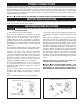
EXTENSION CORDS Use proper extension cords. Make sure your extension cord is in good condition and is a 3-wire extension cord which has a 3-prong grounding type plug and matching receptacle which will accept the machine’s plug. When using an extension cord, be sure to use one heavy enough to carry the current of the machine. An undersized cord will cause a drop in line voltage, resulting in loss of power and overheating. Fig. D, shows the correct gauge to use depending on the cord length.
CARTON CONTENTS INSTRUCTIONS LISTED AND SHOWN IN THIS MANUAL REFER TO BOTH THE 32-325 13-SPINDLE LINE BORING MACHINE AND 32-326 13-SPINDLE PNEUMATIC LINE BORING MACHINE UNLESS OTHERWISE NOTED. For Model 32-325 13-Spindle Line Boring Machine 1 2 5 3 4 8 6 7 Fig.
For 32-326 13-Spindle Pneumatic Line Boring Machine 10 - Pneumatic Boring Machine 10 11 11 - Fence 12 - Table 13 - Clear Plastic Guard 14 - Table Brackets 15 - Wrench 12 16 - Gage for Aligning Fence to Drill Head 15 16 13 14 Fig.
ASSEMBLY FOR YOUR OWN SAFETY, DO NOT CONNECT THE MACHINE TO THE POWER SOURCE UNTIL THE MACHINE IS COMPLETELY ASSEMBLED AND YOU READ AND UNDERSTAND THE ENTIRE INSTRUCTION MANUAL. ACCESSORY 32-331 STAND A B If you purchased the accessory 32-331 steel stand for use with your boring machine, assemble the stand as shown in Fig. 6, using thirty-two 5/8" long carriage bolts, flat washers and hex nuts.
B C A Fig. 8 Fig. 9 TABLE TO MACHINE F 1. Clip the two table slides (A) Fig. 8, to the table bracket (B) as shown. C 2. Clip the remaining two table slides to the other table bracket in the same manner. 3. Center table (C) Fig. 9, on the machine frame as shown. B 4. Position table bracket (B) Fig. 10, against machine frame (D) and underneath table (C) as shown, lining up the two holes (E) Fig. 11, in the table with the two holes (F) Fig. 10, on top of table bracket (B) Fig. 10. D Fig. 10 5.
FENCE TO MACHINE 1. Place spacer (A) Fig. 14, over hole (B) in table bracket with large countersunk end of spacer (A) in the up position. 2. Place a 1/4" lockwasher (C) Fig. 14, and a 1/4" flat washer (D) on the 1/4-20x1-1/2" hex head screw (E) and insert screw (E) up through hole (B) in table bracket and through hole in spacer (A). Thread screw (E) into threaded hole (F) on bottom of fence. NOTE: DO NOT TIGHTEN HARDWARE AT THIS TIME. A F E D B C Fig. 14 3.
E F B H A L K G F G Fig. 18 4. With index pins (B) Fig. 18, engaged with holes in gage (A), loosen table lock knobs, one of which is shown at (E), and move table until front end of fence (F) is approximately 1/32" away from gage at point (G) on each end of the gage. Then tighten the table lock knobs (E). 5. Using a small “C” clamp (not supplied), secure table bracket (K) Fig. 18, to machine frame (L) at a point between the two sides to avoid movement.
C A B A Fig. 22 Fig. 23 ASSEMBLING HEAD LOWERING AND RAISING HANDLE (For 32-325 Line Boring Machine Only) 1. Remove retaining ring (A) Fig. 22, and remove connecting pin (B). 2. Insert end of handle (C) Fig. 23, into head assembly as shown and fasten handle in place by reassembling connecting pin that was removed in STEP 1, through hole in end of handle. Replace retaining ring (A). A B Fig. 24 ASSEMBLING HEAD LOWERING AND RAISING AIR CYLINDER D (For 32-326 Pneumatic Line Boring Machine Only) 1.
G E S K F D L H V N R R A B Fig. 27 4. Make certain air cylinder rod is retracted completely into cylinder (E) Fig. 27. Loosen locknut (K) Fig. 27, and unscrew hex end of clevis rod (L) until holes line up with holes in bracket (N). Using retaining clip (A) and retaining pin (B), which were removed in STEP 1, fasten clevis (L) to bracket (N). Retighten locknut (K) Fig. 27. NOTE: It may be necessary to loosen screws (R) Fig. 28, in order to get pin to line up with clevis. Fig. 28 A B 5.
3. Remove jam nut (D) Fig. 31, from bottom end of air cylinder clamp (E) and assemble air cylinder clamp (E) Fig. 32, to clamp bracket (A) Fig. 31, using jam nut (D). Thread rubber foot (F) Fig. 32, onto bottom of air cylinder clamp (E) as shown. Assemble remaining air cylinder clamp to other clamp bracket in the same manner. G H E 4. Insert red air lines (G) Fig. 33, into air fittings (H) located on top of each air cylinder clamp (E). Push end of air line (G), as far as it will go into fitting (H).
ALIGNING BORING BITS (For 32-325 Line Boring Machine Only) 1. Place a flat piece of wood (A) Fig. 37, on the table and against the fence as shown. Pull operating handle downward until ANY ONE boring bit (B) first contacts the top of the wood surface (A). NOTE: If all boring bits (B) contact the top surface of the wood at the same time, no alignment is necessary. 2. If any of the boring bits (B) Fig. 37, are not contacting the wood surface (A), remove each bit that does not contact the board one at a time.
CONNECTING AIR TO MACHINE (For 32-326 Pneumatic Line Boring Machine Only) A 1/4" female pipe thread (A) Fig. 43, is provided on the air filter for connecting the air line to the machine. An air supply of 90 psi is recommended for best results and this air supply must not exceed 125 psi. A Fig. 43 ADJUSTING AIR PRESSURE (For 32-326 Pneumatic Line Boring Machine Only) An air pressure gage (A) Fig. 44, and regulator (B) are supplied to regulate the air pressure used to operate the machine.
STARTING AND STOPPING MACHINE (For 32-326 Pneumatic Line Boring Machine Only) B A 1. Plug the motor cord (A) Fig. 46, into outlet (B) located on rear of the air and electric control box as shown. 2. Move the motor on-off switch (C) Fig. 47, to the “ON” position. The motor will not start at this time. MAKE SURE THE AREA UNDER THE HEAD IS FREE OF ALL OBSTACLES AND HANDS BEFORE PRECEDING TO THE NEXT STEP. Fig. 46 3. Press in and hold the start button (D) Fig. 47.
MULTI-POSITION LOWERING HANDLE B (For 32-325 Line Boring Machine Only) For extra leverage when boring holes, the handle (B) Fig. 50, can be pulled out as desired to increase leverage, as shown. To move the handle (B) out of the way when not in use, simply push in on handle. CONTROLLING DOWNWARD TRAVEL OF BORING HEAD Fig. 50 (For 32-325 Line Boring Machine Only) A stop is provided to set the depth of the boring bits above the table surface.
2. IMPORTANT: Before setting the limit switch depth setting, make certain all assembly instructions for PNEUMATIC LINE BORING MACHINES detailed in the instruction manual have been completed. Read and understand “STARTING AND STOPPING INSTRUCTIONS FOR PNEUMATIC LINE BORING MACHINES”, before continuing these instructions. C M L E Setting Limit Switch (Depth Control) 3. Place a test board (F) Fig. 54, long enough to reach both clamp cylinders (G), against the fence and under the boring bits as shown.
FENCE STOPS Two fence stops, one right (A) Fig. 58, and one left (B), are supplied with your boring machine. A scale (D) is provided on the fence which has a “0” mark in the center and extends 15 inches out to the left and right. The stops (A) and (B) can be moved anywhere along the fence by loosening lock handles (C), moving the stops (A) and (B), and tightening lock handles (C).
OPERATIONS LINE BORING 1. Figure 63 illustrates a typical line boring operation being performed on a workpiece. Note that the right end of the workpiece is positioned against the fence stop (A) and 13 holes are being bored with a 32mm center distance between each hole. A Fig. 63 2. If more than 13 holes are required, simply slide work-piece along the fence and push down on the indexing pin (B) Fig. 64, until the pointed end of the pin is in the last hole that was previously bored.
CORRECT OPERATING TECHNIQUE (For 32-326 Pneumatic Line Boring Machine Only) The following is a typical example of a line boring operation and how the electric/air controls function: 1. Place the workpiece (A) on the table and against the fence as shown in Fig. 66. A Fig. 66 B 2. Depress and hold the start button (B) Fig. 67. As soon as the start button (B) has been depressed, the two air clamps (C) will activate and the air clamp plungers (C) will lower, holding the workpiece firmly against the table.
NOTES 24
NOTES 25
NOTES 26
ACCESSORIES A complete line of accessories is available from your Delta Supplier, Porter-Cable • Delta Factory Service Centers, and Delta Authorized Service Stations. Please visit our Web Site www.deltamachinery.com for a catalog or for the name of your nearest supplier. Since accessories other than those offered by Delta have not been tested with this product, use of such accessories could be hazardous. For safest operation, only Delta recommended accessories should be used with this product.
PORTER-CABLE • DELTA SERVICE CENTERS (CENTROS DE SERVICIO DE PORTER-CABLE • DELTA) Parts and Repair Service for Porter-Cable • Delta Machinery are Available at These Locations (Obtenga Refaccion de Partes o Servicio para su Herramienta en los Siguientes Centros de Porter-Cable • Delta) ARIZONA Tempe 85282 (Phoenix) 2400 West Southern Avenue Suite 105 Phone: (602) 437-1200 Fax: (602) 437-2200 CALIFORNIA Ontario 91761 (Los Angeles) 3949A East Guasti Road Phone: (909) 390-5555 Fax: (909) 390-5554 San Leandro