
Instruction manual


15
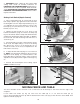
Fig. 33
E
H
G
Fig. 34
Fig. 35
Fig. 36
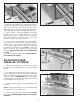
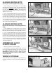
ASSEMBLING AIR FILTER
(For 32-326 Pneumatic Line Boring Machine
Only)
Thread air filter (A) Fig. 34, onto threaded stud (C) on side
of air and electric control box (B) as shown. A 1/4"
female pipe thread is supplied on both sides of the air
filter for connecting the air filter to the threaded stud as
shown, and for connecting air to the machine. NOTE: An
air flow directional arrow is supplied on the filter to help
insure correct assembly. NOTE: Quick connect (D) is not
supplied with the machine.
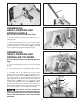
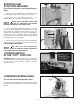
ASSEMBLING BORING BITS
TO SPINDLES
NOTE: THIS MACHINE WILL ONLY ACCEPT BITS
WITH 10MM SHANKS.
1. Thirteen set screws (A) are supplied with your
machine and are to be threaded partway into each
spindle, as shown in Fig. 35, with T-wrench supplied.
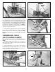
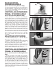
2. Insert boring bits (B) Fig. 36 (not supplied with boring
machine), into spindles (C). Push bit (B) in as far as
possible and tighten set screws (A) against flat on bit.
NOTE: With the 13-Spindle Boring Machine, thirteen bits
are required, seven right hand rotation and six left hand
rotation. A right hand rotation bit is inserted into the
center spindle and every other spindle to the right and
left. Insert left hand rotation bits into the remaining
spindles. Fig. 36 illustrates all thirteen bits assembled to
the boring head.
A
A
C
B
A
B
D
C
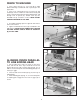
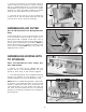
3. Remove jam nut (D) Fig. 31, from bottom end of air
cylinder clamp (E) and assemble air cylinder clamp (E)
Fig. 32, to clamp bracket (A) Fig. 31, using jam nut (D).
Thread rubber foot (F) Fig. 32, onto bottom of air cylinder
clamp (E) as shown. Assemble remaining air cylinder
clamp to other clamp bracket in the same manner.
4. Insert red air lines (G) Fig. 33, into air fittings (H)
located on top of each air cylinder clamp (E). Push end
of air line (G), as far as it will go into fitting (H).