
Manual
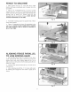
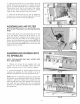


3. Removejamnut(D)Fig.31,frombottomendof air
cyiinderchamp(E)andassembbair cyiinderchamp(E)
Fig.32,to champbracket(A)Fig.31,usingjamnut(D).
Threadrubberfoot(F)Fig.32,ontobottomofaircyiinder
champ(E)as shown.Assembbremainingair cyiinder
champto otherchampbracketinthesamemanner.
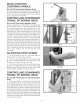
4. insertredair lines(G)Fig.33, into airfittings(H)
locatedontop of eachaircylinderclamp(E).Pushend
ofairline(G),asfarasit wiiigointofitting(H).
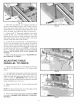
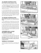
ASSEMBLING AmRFILTER
{For 32-326 Pneumatic Line Boring Machine
Onmy)
Thread air filter (A) Fig. 34, onto threaded stud (C) on side
of air and electric control box (B) as shown. A 1/4"
female pipe thread is supplied on both sides of the air
filter for connecting the air filter to the threaded stud as
shown, and for connecting air to the machine. NOTE: An
air flow directional arrow is supplied on the filter to help
insure correct assembly. NOTE: Quick connect (D) is not
supplied with the machine.
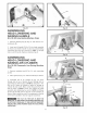
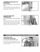
ASSEMBUNG BORING BITS
TO SPINDLES
NOTE: TH_S MACHINE WILL ONLY ACCEPT BraTS
WITH 10MM SHANKS.
1. Thirteen set screws (A) are supplied with your
machine and are to be threaded partway into each
spindle, as shown in Fig. 35, with T-wrench supplied.
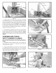
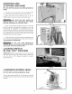
2. Insert boring bits (B) Fig. 36 (not supplied with boring
machine), into spindles (C). Push bit (B) in as far as
possible and tighten set screws (A) against fiat on biL
NOTE: With the 13-Spindle Boring Machine, thirteen bits
are required, seven right hand rotation and six left hand
rotation. A right hand rotation bit is inserted into the
center spindle and every other spindle to the right and
left. Insert left hand rotation bits into the remaining
spindles. Fig. 36 illustrates all thirteen bits assembled to
the boring head.
15
Fig. 33
Fig. 34
Fig. 35
Fig. 36