
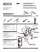
Installation Instructions


E.
10
3
7
53916 Rev. D
D.
A.
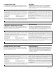
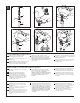
Remove stopper (1), brass nut & washer
(2), black gasket (3) and tail piece (4).
B.
!PPLYSILICONETOUNDERSIDEOFFLANGE)NSERT
flange into sink.
C.
Install black gasket (3), washer and brass nut (2) onto
flange (5) from below sink but do not tighten brass
nut (2). Screw on tail piece (4) and hand tighten.
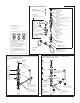
D.
7ITHPIVOTFACINGTOWARDFAUCETPULL
pop-up straight down into drain hole and secure
GASKETBRASSNUTANDWASHER$/./4
452.0/0507(),%4)'(4%.).'"2!33.54
/23%!,!.4-!9./43%!,$2!).2EMOVE
EXCESSSEALANT
Pop-Ups with Metal Flange and Plastic Tail Piece
Renvoi mécanique avec collerette en métal et raccord droit de vidange en plastique
A.
%NLEVEZLABONDELÏCROUENLAITONETLA
rondelle (2), le joint noir (3) et le raccord droit
de vidange (4).
B.
!PPLIQUEZDECOMPOSÏËLASILICONESOUSLA
collerette (5). Introduisez la collerette
dans l’évier.
C.
Montez le joint noir (3), la rondelle et l’écrou en
laiton (2) sur la collerette (5) par dessous l’évier
sans serrer l’écrou en laiton (2).
6ISSEZLE
raccord droit de vidange (4) et serrez-le à
la main.
C.
F.
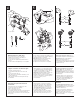
E.
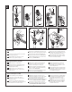
Remove pivot nut (7). Install horizontal rod (8) and
stopper (1) as removable (9) or non-removable (10).
(ANDTIGHTENPIVOTNUT
F.
!TTACHHORIZONTALRODTOSTRAPUSINGCLIP
)NSTALLLIFTRODTIGHTENSCREW#ONNECT
assembly to drain.
A.
1UITEELTAPØNLATUERCADEBRONCEYLA
arandela (2), el empaque negro (3) y la pieza
de cola (4).
B.
!PLIQUESILICØNPORDEBAJODELABRIDA
Introduzca la brida dentro del lavamanos.
C.
Instale el empaque negro (3), la arandela
y la tuerca de bronce (2) en la brida (5) desde
la parte interior del lavamanos pero no apriete
LATUERCADEBRONCE!TORNILLELAPIEZADE
cola (4) y apriete a mano.
D.
#ONELPIVOTEDEFRENTEALALLAVEHALEEL
desagüe automático directamente hacia abajo
dentro del drenaje y fije el empaque (3), la tuerca
DEBRONCEYLAARANDELA./')2%%,
$2%.!*%!54/-«4)#/-)%.42!3!02)%4%,!
45%2#!$%"2/.#%/%,3%,,!$/205%$!
./3%,,!2%,$2%.!*%1UITEELEXCESO
de sellador.
Drenajes automáticos con brida de metal y la pieza de cola plástica
E.
1UITELATUERCADELPIVOTE)NSTALELABARRAHORI-
zontal (8) y el tapón (1) como desmontable (9) o
FIJO!PRIETEAMANOLATUERCADELPIVOTE
F.
Una la barra horizontal (8) a la barra chata (11)
utilizando el gancho (8). Instale la barra de alzar
APRIETEELTORNILLO#ONECTEELENSAMBLE
al desagüe.
D.
!LORSQUELEPIVOTFAITFACEAUROBINETTIREZLE
renvoi directement vers le bas dans l’orifice de
LÏVIERPUISFIXEZLEJOINTLÏCROUENLAITONETLA
RONDELLE.%4/52.%:0!3,%2%.6/)
0%.$!.415%6/533%22%:,²#2/5 %.
,!)4/.#!2,%#/-0/3² À ,!3),)#/.%
0/522!.%0!3!3352%2,²4!.#(²)4²
$52%.6/)%NLEVEZLEXCÒSDECOMPOSÏ
d’étanchéité.
E.
%NLEVEZLÏCROUDUPIVOT)NSTALLEZLATIGE
horizontale (8) et la bonde (1) de manière que la
bonde soit amovible (9) ou non amovible (10).
Serrez l’écrou (7) du pivot à la main.
F.
&IXEZLATIGEHORIZONTALEAUFEUILLARDË
l’aide de l’agrafe (8). Installez la tige de
MANOEUVREETSERREZLAVIS&IXEZ
l’ensemble au renvoi.
1
4
2
3
A.
SILI
CO
NE
B.
5
5
3
2
4
6
3
2
7
1
8
11
12
8
9