
Instruction manual


10
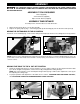
The saw is equipped with two fences. The fence that is
shipped bolted to the table should remain and needs no
adjusting. The other fence piece (A) Fig. 7 is adjustable
and should be placed as close to the blade as possible
for all bevel or straight cuts to provide adequate support
and for an accurate cut.
To adjust, place fence piece (A) into guide groove
(B) and move it to the desired location. Insert knob (C)
to lock in place.
NOTE: The guide groove of the fence can become clogged
with sawdust. Be sure to clean it out periodically.
MAKE SURE THAT THE FENCE IS CLEAR OF THE GUARD AND BLADE BEFORE OPERATING
THE SAW.
Before operating your compound miter saw, firmly mount
it to a workbench or other supporting surface. Four holes
(two of which are shown at (A) Fig. 8) are provided for
fastening the saw to a supporting surface.
When frequently moving the saw from place to place,
mount the saw to a 3/4” piece of plywood. The saw
can then be easily moved from place to place and the
plywood can be clamped to the supporting surface
using “C” clamps.
C
A
Fig. 7
FASTENING THE MACHINE TO A SUPPORTING SURFACE
FENCE OPERATION
A
OPERATION
OPERATIONAL CONTROLS AND ADJUSTMENTS
Fig. 8
B
A
STARTING AND STOPPING THE MACHINE
To start the machine, depress switch trigger (A) Fig. 9. To
stop the machine, release the switch trigger.
This saw is equipped with an automatic electric blade
brake. As soon as the switch trigger (A) Fig. 9 is released,
the electric brake is activated and stops the blade.
Fig. 9 Fig. 10
A turning saw blade can be dangerous. After completing the cut, release the switch trigger (A) Fig.
9 to activate blade brake. Keep cuttinghead down until the blade has come to a complete stop.
The torque developed during braking may loosen the arbor screw. The arbor screw should be
checked periodically and tightened if necessary.
LOCKING THE SWITCH IN THE “OFF” POSITION
IMPORTANT: When the machine is not in use, the switch should be locked in the “OFF” position to prevent unauthorized
use,
using a padlock (B) Fig. 10 with a 3/16" diameter shackle.
In the event of a power outage, always lock switch in “OFF” position until the main power
is restored.
DISCONNECT MACHINE FROM POWER SOURCE.
B