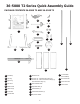
36-5000 T2 Series Quick Assembly Guide PACKAGE CONTENTS 36-5000 T2 AND 36-5100 T2 PC11 PC5 PC12 PC6 PC1 PC13 PC7 PC14 PC15 PC8 PC17 PC18 PC9 PC2 PC3 PC16 PC4 PC10 PC16 10 inch Blade PC1 Saw Body PC9 Blade Wrench PC2 Left Leg PC10 36-5000 T2 - Steel Extension Wings (3) PC3 Right Leg PC19 (Pre-Installed) 36-5100 T2 - Cast Iron Extension Wings (2), Steel Extension Wings (1) PC4 Rip Fence PC11 Anti-Kickback Pawls PC5 Blade Guard PC12 Adjustable Feet (2) PC6 Miter Gauge PC13 Fixed W
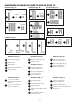
HARDWARE PACKAGE 36-5000 T2 AND 36-5100 T2 Hardware Bag “B” Hardware Bag “A” 006134 003578 005733 HP1 Hardware Bag “D” HP2 007188 005733 003059 HP3 HP15 006111 Hardware Bag “C” 006122 007187 005679 HP4 HP7 HP2 HP6 007187 HP14 HP7 Hardware Bag “E ” HP5 006054 006111 HP14 HP18 006110 HP19 007191 HP24 Hardware Bag “G” Hardware Bag “F” 006111 007187 HP14 HP7 HP20 HP21 007083 007080 Hardware Bag “A” HP22 HP23 007082 007188 HP15 HP25 007081 007193 Hardware Bag “D” Hardwa
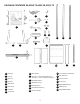
PACKAGE CONTENTS 36-5052 T2 AND 36-5152 T2 PC11 PC5 PC12 PC6 PC1 PC13 PC7 PC14 PC15 PC8 PC17 PC18 PC19 PC9 PC2 PC3 PC16 PC4 PC10 PC20 PC21 PC22 PC1 Saw Body PC9 Blade Wrench PC16 10 inch Blade (Pre-Installed) PC2 Left Leg PC10 36-5052 T2 - Steel Extension Wings (2) PC17 Rear Fence Rail PC3 Right Leg PC4 Rip Fence PC5 Blade Guard PC6 Miter Gauge PC7 Push Stick PC8 Throat Plate 36-5152 T2 - Cast Iron Extension Wings (2) PC11 Anti-Kickback Pawls PC12 Adjustable Feet (2) PC13 Fixed
HARDWARE PACKAGE 36-5052 T2 AND 36-5152 T2 Hardware Bag “A” 007187 006134 003578 005733 HP1 Hardware Bag “C” Hardware Bag “B” HP2 003059 HP3 HP7 005733 HP2 HP6 007191 HP24 Hardware Bag “E ” 006265 006122 HP4 007188 007187 006264 HP11 HP10 Hardware Bag “D” 005679 006263 HP9 HP5 HP15 HP7 HP12 006111 006110 006054 HP18 HP16 HP7 Hardware Bag “G” 006268 HP14 HP19 003059 007187 006262 Hardware Bag “F” 006111 HP17 HP14 006267 HP20 HP21 HP22 HP23 006266 HP25 007196 00
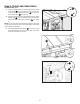
TOOLS REQUIRED FOR ASSEMBLY (not included) PC3 • Flat head screwdriver • 3/8 inch wrench • Phillips head screwdriver • 7/16 inch wrench • 8mm wrench • • 10mm wrench Framing (Carpenter’s) Square Combination Square Straight Edge • 12mm wrench • • 13mm wrench • HP1 PC2 HP3 HP2 • DO NOT lift saw without help. Hold it close to your body while lifting. KEEP knees bent and lift with your legs, not your back. • Fully assemble saw with leg assembly prior to use.
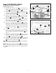
Step 3: FRONT AND REAR RAILS Hardware Bag “C, D” HP14 1. Using the supplied 3/16 inch T-Handle Allen Wrench, attach the Front Rail PC18 [1] to the table front with two 5/16-18 x 1 1/8 inch Flat Countersunk Hex Screw HP15 and two 5/1618 Hex Flange Nuts HP14 . See Figure 5. Front Rail 2. Using the supplied 3/16 inch T-Handle Allen Wrench, attach the Rear Rail PC17 1 [2] to the table back using two 5/16-18 x 7/8 inch Hex Screw with Split Lock Washer 7. HP7 HP15 .
Step 4: EXTENSION WINGS For Models with Three Extension Wings Hardware Bag “C, D, G” PC10 3 1. Attach the left extension wing PC10 [3] to the front rail using two 5/16-18 x 1-1/8 inch Flat Countersunk Hex Screws HP15 and 5/16-18 Hex Flange Nuts HP14 . 2. Attach the left extension wing PC10 LEFT EXTENSION WING [3] to the rear rail using two 5/16-18 x 7/8 Hex Screws w/ Split Lock Washers HP7 and 5/16-18 Hex Flange Nuts HP14 . RIGHT EXTENSION WING PC10 3.
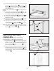
Step 5: EXTENSION WINGS For the 36-5052 T2 and 36-5152 T2 Hardware Bag “D” 1. Attach both extension wings PC10 PC10 [3] to the front rail using four 5/16-18 x 1-1/8 inch Flat Countersunk Hex Screws HP15 and 5/16-18 Hex Flange Nuts HP14 . PC10 2. Attach both extension wings RULER 3 3 RIGHT EXTENSION WING LEFT EXTENSION WING [3] to the rear rail using four 5/16-18 x 7/8 Hex Screws w/ Split Lock Washers HP7 and 5/16-18 Hex Flange Nuts HP14 . PC10 3.
5. Loosely assemble three 5/16-18 x 7/8 inch Hex Head Screws with Split Lock Washers HP7 , 8 x 16 x 1t Flat Washers HP16 and three 5/16-18 Hex Flange Nuts HP14 into the three holes into the side of the extension wing as shown. See Figure 12. NOTE: The 5/16-18 Hex Flange Nuts HP14 are only used on the 365052 T2. 6. Carefully lower the slotted wing attachment PC22 down onto the screws on the extension wing. Tighten the screws after the wood table is leveled with the extension wing. 7.
Step 8: INSTALLING THE HANDLES Elevation and Bevel Hand Wheels The elevation and Bevel Handles are packaged together in the box, please install as follows: 1. Insert one Handle PC14 to the Elevation Hand Wheel located in the front of the Saw, as seen in Figure 17. 2. Insert one Handle to the Bevel Hand Wheel located on the right side of the Saw, as seen in Figure 18.
Step 12: ANTI-KICKBACK PAWLS To reduce the risk of serious personal injury, Anti-Kickback Pawls MUST be in place when making a through cut. A B 1. See Figure 22 and locate the Anti-Kickback Pawls Mounting Slot A in the middle of the top edge of the Riving Knife. 2. Slide Slot in the middle of the Anti-Kickback Pawls Assembly PC11 along the top of the Riving Knife until the stem B locates the center slot A on the Riving Knife. 3.