
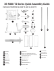
Instructions / Assembly


10
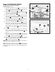
Step 10: THROAT PLATE
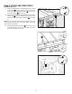
Step 8: INSTALLING THE HANDLES
Elevation and Bevel Hand Wheels
The Rip Fence Handle is packaged individually and labeled
accordingly, please install as follows:
1. Screw the Labeled Handle
PC15
to the Rip Fence with the
supplied Hex Wrench. See in Figure 18.
Step 9: INSTALLING THE RIP
FENCE HANDLE
NOTE: Refer to Operator's Manual for storage locations - Wrenches,
Blade Guard, Anti-kick back pawls, and Push-stick.
NOTE: Refer to Operator's Manual page 23 for throat plate
instillation instructions.
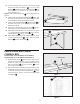
IMPORTANT: Before raising Blade you must release Bevel Lock
and tilt Blade 45° and remove styrofoam block under Motor
Housing. See Figure 19.
To reduce the risk of serious personal
injury, the Riving Knife MUST be installed and properly
positioned for every possible through and non-through cut.
1. Your Saw is shipped with the Blade and Riving Knife
installed and properly aligned. The Riving Knife comes
installed in the low, non-through cutting position. Prior to
operating your Saw, check to make sure the alignment
of the Blade to the Miter Slot and the Riving Knife to the
Blade was not affected by shipping. To check alignment of
the Blade and Riving Knife, see page 27 in the Assembly
section of the Operator’s Manual.
2. The Riving Knife comes installed in the low, non-through
cutting position. To attach the Anti-Kickback Pawls and
Blade Guard Assemblies, the Riving Knife MUST be in
the raised position as shown in Figure 38, page 32 of the
Operator’s Manual. To raise and lower the Riving Knife, see
Riving Knife Height Settings on page 32.
3. When installing Riving Knife, Anti-Kickback Pawls and Blade
Guard, Blade MUST be at 90° setting and raised to the
maximum height. See “RAISING AND LOWERING BLADE”
section on page 30 of the Operator’s Manual.
Step 11: BLADE AND RIVING KNIFE
The elevation and Bevel Handles are packaged together in the box,
please install as follows:
1. Insert one Handle
PC14
to the Elevation Hand Wheel located
in the front of the Saw, as seen in Figure 17.
2. Insert one Handle
PC14
to the Bevel Hand Wheel located on
the right side of the Saw, as seen in Figure 18.
Figure 17
Figure 18
PC14
PC14
PC15
Figure 19
(REMOVE)(REMOVE)