
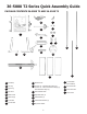
Instructions / Assembly


8
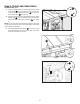
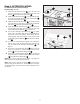
Step 5: EXTENSION WINGS
Figure 10
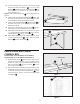
Step 6: WOOD EXTENSION TABLE
For the 36-5052 T2 and 36-5152 T2
Hardware Bag “E”
1. Lay the Wood Table Extension
PC20
upside down on oor or
bench.
2. Position table legs
PC21
in corner as shown in Figure 11 the
vertical wall of the angle plate on the leg should be against
the end wood wall of the table.
3. Fasten the legs to the table board with eight 8-16 x 3/4
Round Head Phillips Screw
HP12
.
4. Feed four 10-32 x 34.5mm Round Head Phillips Screw
HP9
with four 7/32 x 1/2 Flat Washers
HP10
and 10-32 Hex Nut
HP11
through the drilled holes from the outside, then
assemble the nuts onto the screws and tighten.
Figure 11
3
3
LEFT EXTENSION LEFT EXTENSION
WING WING
RIGHT EXTENSION RIGHT EXTENSION
WING WING
RULER
PC20
PC21
HP9
HP12
PC10
PC10
1. Attach both extension wings
PC10
[3] to the front rail using
four 5/16-18 x 1-1/8 inch Flat Countersunk Hex Screws
HP15
and 5/16-18 Hex Flange Nuts
HP14
.
2. Attach both extension wings
PC10
[3] to the rear rail using
four 5/16-18 x 7/8 Hex Screws w/ Split Lock Washers
HP7
and 5/16-18 Hex Flange Nuts
HP14
.
3. Attach both right extension wings
PC10
[3], to the Front and
Rear rails using four 5/16-18 x 1-1/8 inch Flat Countersunk
Hex Screw
HP15
and 5/16-18 Hex Flange Nuts
HP14
.
4. Attach the extension wings
PC10
[3] to the table using three
5/16-18 x 7/8 inch Hex Head Screws with Split Lock
Washers
HP7
for each wing. See Figure 10.
NOTE: Use a ruler to make sure the top edges of the wings are
flush with the top of the tabletop. See Figure 10.
NOTE: There are four 5/16-18 Set Screws
HP24
for the cast iron
extension wings for the 36-5100 T2. Two Set Screws for each cast
iron Extension Wing. The set screws are used to adjust the level.
See Figure 9.
For the 36-5052 T2 and 36-5152 T2
Hardware Bag “D”