0-INCH CONTRACTOR TABLE SAW Scie de table de 10 pouces (254 mm) pour entrepreneurs Sierra de mesa de 10 pulgadas (254 mm) para contratista 36-5000 T2 36-5100 T2 Français (34) Español (65) 36-5052 T2 www.DeltaMachinery.com 36-5152 T2 Instruction Manual Manuel d’utilisation Manual de instrucciones To reduce risk of serious injury, thoroughly read and comply with all warnings and instructions in this manual and on product.
TABLE OF CONTENTS IMPORTANT SAFETY INSTRUCTIONS..............................3 OPERATION.....................................................................22 SAFETY LOGOS ...............................................................3 STARTING AND STOPPING THE SAW...............................22 GENERAL POWER TOOL SAFETY RULES ..........................4 OVERLOAD PROTECTION...............................................23 TABLE SAW SAFETY RULES ..............................................
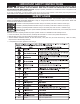
IMPORTANT SAFETY INSTRUCTIONS CAREFULLY READ AND FOLLOW ALL WARNINGS AND INSTRUCTIONS ON YOUR PRODUCT AND IN THIS MANUAL. SAVE THIS MANUAL. MAKE SURE ALL USERS ARE FAMILIAR WITH IT’S WARNING AND INSTRUCTIONS WHEN USING THE TOOL. Improper operation, maintenance or modification of tools or equipment could result in serious injury and/or property damage.
GENERAL POWER TOOL SAFETY WARNINGS Read all safety warnings, instructions, illustrations and specifications provided with this power tool. Failure to follow all instructions listed below may result in electric shock, fire and/or serious injury. Save all warnings and instructions for future reference. The term “power tool” in the warnings refers to your mains-operated (corded) power tool or BATTERY-operated (cordless) power tool. 1. Work area safety 2. 3. 4. 5. a. Keep work area clean and well lit.
TABLE SAW SAFETY RULES Failure to follow these rules may result in serious personal injury. • SEE GENERAL POWER TOOL SAFETY SECTION OF THIS MANUAL. Read entire instruction manual before operating saw. Learning the saw’s proper applications, limitations, and specific potential hazards will greatly minimize the possibility of accidents and injury. Make sure all users are familiar with its warnings and instructions before using saw.
TABLE SAW SAFETY RULES j. Feed workpiece at an even pace. Do not bend or twist the workpiece. If jamming occurs, turn the tool off immediately, unplug the tool then clear the jam. Jamming the saw blade by the workpiece can cause kickback or stall the motor. k. Do not remove pieces of cut-off material while the saw is running. The material may become trapped between the fence or l. inside the saw blade guard and the saw blade pulling your fingers into the saw blade.
PROPOSITION 65 WARNING: Some dust created by power sanding, sawing, grinding, drilling, and other construction activities contains chemicals known to the state of California to cause cancer, birth defects or other reproductive harm.
POWER CONNECTIONS Check with a qualified electrician or service personnel if the grounding instructions are not completely understood, or if in doubt as to whether the machine is properly grounded. Use only 3-wire extension cords that have 3-prong grounding type plugs and matching, properly grounded 3-conductor receptacles that accept the machine’s plug, as shown in Figure A, or a properly grounded receptacle with a grounding means adapter, as shown in Figure B.
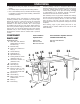
UNPACKING • The machine is heavy, two people are required to unpack and lift. • Use a safety strap to avoid tip over when lifting machine. • Prior to tool assembly and use, read this manual thoroughly to familiarize yourself with proper assembly, maintenance and safety procedures. Compare package contents to Component Parts List and Hardware Package List prior to assembly to make sure all items are present. Carefully inspect parts to make sure no damage occurred during shipping.
HARDWARE PACKAGES UNPACKING 30” Fence versions (36-5000 T2 and 36-5100 T2) * Description Item # Parts List Qty.
ASSEMBLY • Do not lift saw without help. Hold it close to your body while lifting. Keep knees bent and lift with your legs, not your back. • Fully assemble saw with leg assembly prior to use. Leg assembly is an integral and necessary part of the support structure for this saw. Avoid contact with blade teeth. Keep blade stored or lowered when possible.
ASSEMBLY FIXED WHEELS AND STATIONARY FEET 1. Attach the two fixed wheels (A) to the two left leg, C opposite the pivot caster, using the M8 X 53 mm axle pin as in Figure 2. 2. Screw the adjustable feet (C) into the threaded inserts in the right leg, next to the pivot caster. 3. Lay a scrap piece of 2x4 in back of the saw, as shown in Figure 3, to prevent damage to the dust chute when righting the saw. 4. Stand the saw right side up.
EXTENSION WINGS ASSEMBLY LEFT EXTENSION WING For Models with Three Extension Wings RIGHT EXTENSION WING 1. Next attach the left side extension wing (3) to the front and rear rails using four (5/16-18 x 1 1/8”) flat head screws, (5/16”) lock washers, and (5/16-18) hex flange nuts. See Figure (9a) 3 2. Attach the left side extension wing (3) to the side of the RULER 3 saw table using three (5/16-18 x 7/8”) hex head screws w/ spring washers. See Figure (9b) 3.
ASSEMBLY 4. Carefully drill through the holes in the vertical angle plate holes and the wood wall of the table with a ¼ inch drill. Feed the #10-32 X 1 1/4” screws with #10 flat washers (E) through the drilled holes from the outside, then assemble the nuts onto the screws and tighten. 5. Loosely assemble three 5/16-18 x 7/8” screws with spring washers, flat washers and nuts (F) into the three holes into the side of the extension wing as shown. (Fig. 11) G F 6.
THROAT PLATE ASSEMBLY 1. To install throat plate, lower blade below tabletop, then carefully feed the throat plate, with plate end first, from the front of the table to the rear, keeping the blade centered within the slot on the throat plate. See Figure 15A. The plate should rest within the cavity in the tabletop on top of 5 flat head screws. 2. Ensure that the throat plate is flush with the top of the table. 3.
ASSEMBLY ANTI-KICKBACK PAWLS AND BLADE GUARD ANTI-KICKBACK PAWLS To reduce the risk of serious personal injury, anti-kickback pawls must be in place when making a through cut. 1. Refer to Figure 16 and locate the anti-kickback pawls mounting slot (A) in the middle of the top edge of the riving knife. 2. Slide slot in the middle of the anti-kickback pawls assembly along the top of the riving knife until the stem (B) locates the center slot on the riving knife. 3.
ASSEMBLY ADJUSTING 90° AND 45° POSITIVE BEVEL STOPS There are positive stops at each end of the bevel range. To ensure accurate cuts, the positive stops must be positioned at exactly at 90° and 45°. The bevel stops are properly adjusted as shipped. However, for maximum accuracy, you should check the position of the stops upon assembly and from time to time to assure that the settings remain satisfactory. To check the position of the stops and adjust if necessary, refer to Figure 18 and do the following.
PREPARING TO CUT RAISING AND LOWERING THE BLADE For most applications, it is recommended that you raise the blade 1/8-inch (3.2mm) to 1/4-inch (6.4mm) above the top surface of the workpiece. Raise or lower the blade with the hand wheel (A) located on the front of the saw maximum 45° (fig 19). B 1. Before raising or lowering the blade, be sure to loosen the lock knob (B) by turning it counterclockwise. 2. To raise the saw blade, turn the hand wheel clockwise.
PREPARING TO CUT SELECTING AND STORING SAW BLADES Riving knives must be matched to saw blade dimensions in order to function effectively. Use only saw blades designed for maximum safe operating speeds of 3,600 RPM or greater. The saw blade furnished with your new saw is a 10-inch (254 mm) combination blade, used for cross cutting (across the grain) and ripping (with the grain) through the workpiece. The arbor hole of the blade is 5/8-inch (16 mm) diameter.
PREPARING TO CUT RIVING KNIFE HEIGHT SETTINGS The height of the riving knife should be adjusted based on the type of cut being made. For all through cuts (when the wood is completely severed), it should be in the raised position, with anti-kickback fingers and guard installed. For non-through cuts (when the blade does not penetrate the top of the workpiece), the riving knife should be in the lowered position and antikickback fingers and guard removed. aligned with the blade.
PREPARING TO CUT/USING THE MITER GAUGE The miter gauge is equipped with adjustable index stops at 90°, 75°, 60°, 45° and 30°. To set the miter for an angled cut, see Figure 25 and: 1. Loosen the handle (A). 2. Depress the thumb lever (B). 3. Move the body of the miter gauge to the desired angle maximum 30° on either side. 4. Release the thumb lever and retighten the handle. The miter gauge is equipped with a washer on the end of the bar which fits into the t-slot in the table.
OPERATION Failure to comply with the following the warnings may result in serious personal injury. READ ENTIRE MANUAL. In addition to reading these operating instructions, it is important to read and understand the entire manual before operating this saw. Follow all applicable instructions regarding assembly, preparation, and adjustment prior to making any cuts and comply with all safety rules and warnings in this section and elsewhere throughout this manual. 4.
OPERATION OVERLOAD PROTECTION Your saw is supplied with overload protection. If the motor shuts off or fails to start due o overloading (cutting stock too fast, using a dull blade, using the saw beyond its capacity, etc.) or low voltage, let the motor cool three to five minutes. Then depress the red reset button (B), reset button (B), on the motor under the saw, shown in Figure 27, and restart the saw. NOTICE: If the motor continually shuts off due to overloading, contact a qualified electrician.
RIP CUTS OPERATION • Rip cutting: Rip cutting is performed predominantly in a parallel direction with the grain of the wood. • Make sure blade is parallel to miter gauge slot prior to cutting. Instructions for adjustment on page 27. 1. 2. 3. 4. 5. 6. 7. 8. 9. 10. 11. 12. Remove miter gauge Make sure bevel angle is set to 0°. Set blade to correct height for workpiece. Install rip fence and lock it down parallel with and at desired distance from blade.
CROSSCUTTING OPERATION • Cross cutting: Cross cutting is performed predominantly in a perpendicular direction with the grain of the wood. • Make sure blade is parallel to miter gauge slot prior to cutting. Instructions for adjustment on page 27. • NEVER use the fence as a guide or length stop when crosscutting.
COMPOUND MITER CUTS OPERATION This is a combination of bevel crosscutting and mitering. Refer to Figure 32 and follow the instructions for both bevel crosscutting and mitering. Remember to use the right miter slot for all bevel cuts. LARGE PANEL CUTS 90º Place workpiece supports at the same height as the saw table behind saw to support the cut workpiece, and alongside (s) of saw, as needed. Depending on shape of panel, use rip fence or miter gauge to control workpiece.
OPERATION HEELING (PARALLELING) BLADE TO MITER GAUGE GROOVE • Blade (A) must be parallel to miter gauge groove so that wood does not bind, resulting in kickback. Failure to do so could result in serious personal injury. • To reduce risk of injury from kickback, align rip fence to blade (A) following any blade adjustments. DO NOT loosen any screws for this adjustment until alignment has been checked with a square to be sure adjustments are necessary. Once screws are loosened, items must be reset.
CUTTING AIDS AND ACCESSORIES AUXILIARY RIP FENCE FACING Use an auxiliary rip fence facing when needed for special cuts, such as ripping material that is thin enough to slide under the rip fence provided with your saw, or when a taller rip fence is necessary to complete your cut. To add an auxiliary wood facing to one or both sides of the rip fence, select a piece of wood with smooth surfaces, Attach the wood to the rip fence with two clamps.
CUTTING AIDS AND ACCESSORIES FEATHERBOARD Featherboards are used to keep the work in contact with the fence and table (Figure 38), and help prevent kickback. Featherboards are especially useful when ripping small workpieces and for completing non-through cuts. The end is angled with a series of narrow slots to give a friction hold on the workpiece, It is locked in place on the table or fence with a c-clamp. 1.
ALIGNMENT RIVING KNIFE ALIGNMENT WITH THE BLADE This procedure requires a 4mm T-handle hex wrench and straight edge ruler. (Fig .40b) WARNING: Completely disconnect saw from power source before making any adjustments. 1. Carefully remove throat plate, 2. Loosen the two hex-head screws (A) shown in Figure A B 36. 3. Using a straight edge ruler, align riving knife with blade body showin in Figure 40a. 4. Tighten the two hex-head screws (A) shown in Figure 36. 5.
ALIGNMENT ALIGNING FENCE PARALLEL TO MITER SLOT ALIGNING FENCE PERPENDICULAR TO THE TABLE 1. Move fence adjacent to right miter gauge and secure to 1. Move fence over the cast iron table and secure to the 2. 2. Use a square to check that the fence face is 3. 4. 5. the guide tube by lowering the fence clamping lever. If the fence face (A) figure 42, is not parallel to the miter slot (B), raise the clamping lever and lift the fence and place it on the saw table.
MAINTENANCE To reduce the risk of injury, turn unit off and disconnect it from power source before cleaning or servicing, before installing and removing accessories, before adjusting and when making repairs. An accidental start-up can cause injury. KEEP MACHINE CLEAN Wear certified safety equipment for eye, hearing and respiratory protection while using compressed air. Periodically blow out all air passages with dry compressed air. All plastic parts should be cleaned with a soft damp cloth.
ACCESSORIES For accessories please visit our Web Site for an on-line catalog or for the name or your nearest supplier. Since accessories other than those offered by DELTA® have not been tested with this product, use of such accessories could be hazardous.
LOGOS DE SÉCURITÉ Pour certaines informations dans ce guide, il est particulièrement important que vous en preniez connaissance et que vous les compreniez. Ces informations concernent VOTRE SÉCURITÉ et la PRÉVENTION DE PROBLÈMES AVEC L’ÉQUIPEMENT. Pour vous aider à reconnaître ces informations, nous utilisons les symboles ci-dessous. Veuillez lire le guide et prêter attention à ces sections. Indique une situation dangereuse imminente qui, si elle n’est pas évitée, entraînera la mort ou des blessures graves.
AVERTISSEMENTS DE SÉCURITÉ GÉNÉRAUX POUR OUTILS ÉLECTRIQUES AVERTISSEMENT : Lisez tous les avertissements, instructions, illustrations et spécifications fournis avec cet outil électrique. Le non-respect de toutes les instructions citées ci-dessous peut causer une décharge électrique, un incendie ou une blessure grave. Conservez tous les avertissements et instructions pour consultation future.
RÈGLES DE SÉCURITÉ DE LA SCIE DE TABLE Le non-respect de ces règles peut provoquer des blessures graves. • • VOIR LA SECTION RÉGLES DE SÉCURITÉ GÉNÉRALES DES OUTILS ÉLECTRIQUES DU PRÉSENT MANUEL. Lisez le manuel d’instructions en intégralité avant d’utiliser la scie. Apprendre la bonne utilisation et les limites de la scie, ainsi que les dangers potentiels connexes, pour minimiser le risque d’accidents et de blessures.
RÈGLES DE SÉCURITÉ DE LA SCIE DE TABLE k. Ne retirez pas des morceaux de matériau découpé pendant que la scie est en marche. Le matériau pourrait se coincer 3. 4. entre le guide ou l’intérieur du protège-lame et la lame de scie, ce qui pourrait entraîner vos doigts vers la lame de scie. Éteignez la scie et attendez que la lame se soit arrêtée avant de retirer le matériau. l. Pour le sciage en long de pièces de moins de 2 mm d’épaisseur, utilisez un guide auxiliaire en contact avec le plateau.
AVERTISSEMENT DE LA PROPOSITION 65 : AVERTISSEMENT : Des poussières créées par le ponçage, sciage, meulage, perçage et autres opérations de construction contiennent des produits chimiques reconnus par l’État de la Californie pour causer le cancer, des malformations congénitales ou autres problèmes de reproduction.
POWER CONNECTIONS Si les consignes de mise à la terre ne sont pas complètement comprises ou en cas de doute concernant la mise à la terre de l’appareil, se renseigner auprès d’un électricien ou du personnel de service agréés. Utiliser uniquement des cordons à 3 fils avec des fiches de mise à la terre à 3 broches et des prises adaptées à la fiche de la machine, comme illustré à la Figure A, ou une prise correctement reliée à la terre avec un adaptateur mis à la terre, comme illustré à la Figure B.
DÉBALLAGE • La machine est lourde, deux personnes sont nécessaires pour la déballer et la soulever. • Placez une courroie de sécurité autour de la machine pour éviter qu’elle bascule lors du levage. • Avant d’assembler et d’utiliser la machine, lisez attentivement ce manuel pour vous familiariser avec les procédures d’assemblage, d’entretien et de sécurité appropriées.
DÉBALLAGE ENSEMBLES DE QUINCAILLERIE Versions avec guide de 30” (36-5000 et 36-5100)* Description Qté. Emplacement d’utilisation Boulon de carrosserie 8mm x 70mm Écrou frein M8 Rondelle à ressort M8 Boulon de carrosserie M6 x 72mm Écrou de blocage M6 Goupille axiale M8 x 53mm Écrou de blocage M8 Vis auto taraudeuse M6 x 10mm à tête Phillips Vis tête hex. 5/16-18 x 7/8” avec rondelle à ressort 1 1 1 4 4 2 2 16 17 Vis à tête bombée 1/4 -20 x ½’’ hex.
MONTAGE MISE EN GARDE : Évitez tout contact avec les dents • • Ne soulevez pas la scie sans aide. Tenez-la près de votre corps en soulevant. Gardez les genoux pliés et soulevez en utilisant les jambes, pas le dos. Assemblez complètement la scie avec le piètement avant de l’utiliser. Le piètement est une partie intégrante et nécessaire de la structure de support de cette scie. ou abaissée si possible. de la lame.
MONTAGE ROULETTES INTÉGRÉES ET PIEDS STATIONNAIRES 1. Fixez les deux roulettes intégrées (A) sur les deux pieds gauches, à l’opposé de la roulette pivotante, à l’aide de la goupille axiale M8 X 53 mm comme sur la Figure 2. 2. Vissez les pieds réglables (C) dans les inserts filetés dans le pied droit, à côté de la roulette pivotante. 3. Placez une plaque métallique de 2x4 à l’arrière de la scie, comme indiqué sur la Figure 3, pour éviter d’endommager le capteur à poussière lors du redressement de la scie.
AILES D’EXTENSION MONTAGE AILE D’EXTENSION GAUCHE Pour les Modèles avec Trois Ailes d’Extension AILE D’EXTENSION DROITE 1. Ensuite, fixez l’aile d’extension latérale gauche (3)sur les rails avant et arrière à l’aide de quatre vis à tête plate (5/16-18 x 1 1/8”), de rondelles de blocage (5/16”) et d’écrous à bride hex. (5/16/18). Voir Figure (9a) 3 2. Fixez l’aile d’extension latérale gauche (3) sur le côté de RÈGLE 3 la table à scie à l’aide de trois vis à tête hex.
MONTAGE 3. Fixez les pieds sur le dessus de la table avec huit vis 4. 5. 6. 7. 8. 9. auto-taraudeuses # 8 x 3/4 “(D). Percez soigneusement au travers des trous dans les trous de la plaque d’angle verticale et la paroi en bois de la table avec un foret de ¼ de pouce. Faites passer depuis l’extérieur les vis #10-32 X 1 1/4” avec des rondelles plates #10 (E) à travers les trous percés, puis assemblez les écrous sur les vis et serrez.
PLAQUE À GORGE MONTAGE 1. Pour installer la plaque à gorge, abaissez la lame en dessous du plateau de la table, puis faites passer soigneusement la plaque à gorge, extrémité fendue d’abord, de l’avant de la table à l’arrière, en gardant la lame centrée dans la fente de la plaque à gorge. Voir Figure 15A. La plaque doit reposer à l’intérieur de la cavité dans le plateau de la table. 2. Assurez-vous que la plaque à gorge est alignée avec la partie supérieure de la table. 3.
MONTAGE DOIGTS ANTI-RETOUR ET PROTÈGE-LAME DOIGTS ANTI-RETOUR Pour réduire le risque de blessures graves, les doigts antiretour doivent être en place lorsque vous effectuez une coupe traversante. 1. Reportez-vous à la Figure 16 et localisez la fente de montage des doigts anti-retour (A) au milieu du bord supérieur du couteau diviseur. 2.
MONTAGE AJUSTEMENT DES BUTÉES FIXES POUR L’ANGLE DE BISEAU DE 90° ET 45° Il y a des butées fixes à chaque extrémité de la plage de biseau. Pour assurer des coupes précises, les butées fixes doivent être positionnées exactement à 90° et 45°. Les butées coniques sont correctement réglées en usine. Cependant, pour une précision maximale, vous devez vérifier la position des butées lors de l’assemblage et de temps en temps pour vous assurer que les réglages restent satisfaisants.
PRÉPARA MONTTION POUR COUPER SOULEVER ET ABAISSER LA LAME Pour la plupart des applications, il est recommandé de soulever la lame de 1/8 pouces (3,2 mm) à ¼ pouces (6,4 mm) au-dessus de la surface supérieure de la pièce. Relevez ou abaissez la lame avec le volant de commande (A) situé à l’avant de la scie maximum 45° (voir Figure 19). B 1. Avant de soulever ou d’abaisser la lame, veillez à desserrer le bouton de verrouillage (B) en le tournant dans le sens antihoraire. 2.
PRÉPARATION POUR COUPER SÉLECTION ET RANGEMENT DES LAMES DE SCIE Les couteaux diviseurs doivent être adaptés aux dimensions de la lame de scie afin de fonctionner efficacement. La lame de scie fournie avec votre nouvelle scie est une lame combinée de 10 pouces (254 mm), utilisée pour la coupe transversale (à travers le grain) et longitudinale (dans le sens du grain) à travers la pièce. L’alésage central de la lame est de 5/8 pouces (16 mm) de diamètre.
PRÉPARATION POUR COUPER RIVING SET HAUTEUR DE COUTEAU nouvelle position; remuer si nécessaire. La hauteur du couteau diviseur doit être ajustée en fonction du type de coupe effectuée. Pour toutes les coupes traversantes (lorsque le bois est complètement coupé), il devrait être en position levée, avec les doigts anti-recul et la protection installés.
PRÉPARATION POUR COUPER Le guide à onglets est équipé de butées d’indexage réglables à 90°, 75°, 60°, 45° et 30°. Pour régler l’onglet en vue d’une coupe en biseau, voir Figure 25 et : 1. Desserrez la poignée (A). 2. Appuyez sur la gâchette de pouce (B). 3. Déplacez le corps du guide à onglets à l’angle désiré maximum 30° de chaque côté. 4. Relâchez la gâchette de pouce et resserrez la poignée.
FONCTIONNEMENT Le non-respect des avertissements suivants peut entraîner des blessures graves. LIRE LE MANUEL EN ENTIER. En plus de lire ces instructions de fonctionnement, il est important de lire et comprendre le manuel en entier avant d’utiliser cette scie.
FONCTIONNEMENT PROTECTION DE SURCHARGE Votre scie est livrée avec une protection contre les surcharges. Si le moteur s’arrête ou ne parvient pas à démarrer en raison d’une surcharge (découpe trop rapide, utilisation d’une lame émoussée, utilisation de la scie au-delà de sa capacité, etc.) ou une basse tension, laissez le moteur refroidir trois à cinq, minutes. Puis appuyez sur le bouton de réinitialisation rouge (B) sur le moteur sous la scie, montré à la Figure 27, et redémarrez la scie.
FONCTIONNEMENT COUPES LONGITUDINALES • • Découpe à la déchirure: la coupe à la déchirure est effectuée principalement dans une direction parallèle au grain du bois. Assurez-vous que la lame est parallèle à la fente du calibre d’onglet avant de couper. Instructions de réglage à la page 58. 1. 2. 3. 4. 5. 6. 7. 8. 9. 10. 11. Retirez le guide à onglets Assurez-vous que l’angle de biseau est réglé sur 0°. Réglez la lame à la hauteur correcte pour la pièce.
COUPE TRANSVERSALE • FONCTIONNEMENT Coupe transversale: La coupe transversale est effectuée principalement dans une direction perpendiculaire au grain du bois. Assurez-vous que la lame est parallèle à la fente du calibre d’onglet avant de couper. Instructions de réglage à la page 58. 7. • NE JAMAIS utiliser le guide comme une butée longitudinale lors des coupes transversales.
FONCTIONNEMENT COUPES D’ONGLETS COMPOSÉES Il s’agit d’une combinaison entre coupe transversale en biseau et coupe d’onglets. Voir Figure 32 et suivre les instructions à la fois pour les coupes transversales en biseau et les coupes d’onglets. N’oubliez pas d’utiliser la fente à droite pour toutes les coupes en biseau.
FONCTIONNEMENT AJUSTER LA LAME PARALLÈLE À LA RAINURE DU GUIDE D'ONGLETS • • A L a lame (A) doit être parallèle à la rainure du guide d'onglets afin d'éviter que le bois se coince, ce qui entraînerait un recul. Le non-respect de cette directive pourrait entraîner des blessures graves. our réduire le risque de blessures causées par P un recul, alignez le guide de refente à la lame (A) après tout ajustement de la lame.
ACCESSOIRES DE COUPE ET ACCESSOIRES REVÊTEMENT AUXILIAIRE DU GUIDE LONGITUDINAL Utilisez un revêtement auxiliaire du guide longitudinal en cas de besoin pour des coupes spéciales, telles que les coupes longitudinales d’un matériau qui est assez mince pour glisser sous le guide longitudinal fourni avec votre scie ou quand un guide longitudinal plus haut est nécessaire pour finaliser votre coupe.
ACCESSOIRES DE COUPE ET ACCESSOIRES PLANCHE À LANGUETTES 1. Choisissez un morceau de bois d’environ ¾ pouce Les planches à languettes sont utilisées pour maintenir la pièce en contact avec le guide et la table (Figure 38) et aider à éviter les rebonds. Les planches à languettes sont particulièrement utiles lors de la coupe longitudinale de petites pièces et pour finaliser des coupes non traversantes.
ALIGNEMENT ALIGNEMENT COUTEAU RIVING AVEC LA LAME Cette procédure requiert une clé hexagonale de 4 mm avec une poignée en T. (Figure 36b) AVERTISSEMENT: Débranchez la scie complètement de la source d’alimentation avant d’effectuer tout réglage. 1. Retirez délicatement la plaque à gorge. 2. Desserrez les deux vis hexagonales (A) comme indiqué 3. 4. 5. 6. 7. dans la figure 1. l’aide d’une règle droite, alignez le couteau diviseur avec la lame comme illustré dans la figure 3.
ALIGNEMENT ALIGNEMENT PARALLÈLE DU GUIDE À LA FENTE À ONGLETS ALIGNEMENT PERPENDICULAIRE DU GUIDE À LA TABLE 1. Déplacez le guide à côté du guide à onglets du côté 2. 3. 4. 5. 1. Déplacez le guide sur la table en fonte et fixez-le au droit et fixez-le au tube de guidage en abaissant le levier de serrage du guide. Si la paroi du guide (A) Figure 42 n’est pas parallèle à la fente (B), soulevez le levier de serrage et levez le guide et placez-le sur la table de sciage.
ENTRETIEN Pour réduire le risque de blessures, éteignez la machine et débranchez-la de la source d’alimentation avant de la nettoyer ou la réparer, installer et retirer des accessoires, ou effectuer des réglages et réparations. Un démarrage inopportun peut provoquer des blessures. GARDER LA MACHINE PROPRE Souffler périodiquement de l’air comprimé sec à l’intérieur de tous les conduits d’air. Toutes les pièces en plastique doivent être nettoyées avec un chiffon doux humide.
ACCESSOIRES Pour les accessoires, veuillez visiter notre site Web pour un catalogue en ligne ou pour le nom de votre fournisseur le plus proche. AVERTISSEMENT : Puisque les accessoires autres que ceux offerts par DELTA® n’ont pas été testés avec ce produit, l’utilisation de ces accessoires peut être dangereuse. Pour une utilisation sécuritaire, seulement les accessoires DELTA ® recommandés doivent être utilisés avec ce produit.
LOGOTIPOS DE SEGURIDAD Este manual contiene información que es importante que usted conozca y entienda. Esta información se refiere a la protección de SU SEGURIDAD y PREVIENE PROBLEMAS DEL EQUIPO. Para ayudarlo a reconocer esta información, usamos los símbolos debajo. Lea el manual y preste atención a estas secciones. PELIGRO: Indica una situación de peligro inminente que, si no se evita, provocará muertes o lesiones graves.
ADVERTENCIAS DE SEGURIDAD DE LA HERRAMIENTA ELÉCTRICA GENERAL ADVERTENCIA: Lea todas las advertencias de seguridad, instrucciones, ilustraciones y especificaciones suministradas con esta herramienta motorizada. No seguir todas las instrucciones detalladas a continuación podría provocar descargas eléctricas, incendios y/o lesiones graves. Guarde todas las advertencias e instrucciones para consulta futura.
REGLAS DE SEGURIDAD DE LA SIERRA DE MESA No seguir estas reglas puede provocar graves lesiones personales. • • CONSULTE LA SECCIÓN DE SEGURIDAD GENERAL PARA HERRAMIENTAS ELÉCTRICAS EN ESTE MANUAL. Lea todo el manual de instrucciones antes de operar la sierra. Conocer las aplicaciones adecuadas,limitaciones y riesgos potenciales específicos de la sierra minimizará en gran medida la posibilidad de sufriraccidentes y lesiones.
REGLAS DE SEGURIDAD DE LA SIERRA DE MESA k. No retire piezas de material de corte mientras la sierra esté en marcha. El material puede quedar atrapado entre la guía o dentro del protector de la hoja de sierra, y la hoja de sierra puede arrastrar sus dedos hacia la hoja de sierra. Apague la sierra y espere hasta que la hoja de sierra se detenga antes de retirar el material. l. Utilice una guía auxiliar en contacto con la cubierta de mesa cuando corte piezas de menos de 2 mm de grosor.
ADVERTENCIA DE LA PROPUESTA 65: ADVERTENCIA: Parte del polvo creado por la lijadora, sierra, esmeriladora, perforadora, y otras actividades de construcción eléctricas contiene químicos, que, según el Estado de California, producen cáncer, defectos de nacimiento, u otro daño reproductivo.
CONEXIONES A LA FUENTE DE PODER Verifique con un electricista calificado o personal de servicio si las instrucciones de conexión a tierra no se entienden por completo o si tiene dudas acerca de si la máquina está correctamente conectada a tierra.
DESEMPAQUE • La máquina es pesada, se necesitan dos personas para desempacarla y levantarla. • Use una correa de seguridad para evitar una volcadura al levantar la máquina. • Antes de ensamblar y usar la herramienta, lea con atención este manual para familiarizarse con los procedimientos adecuados de ensamblado, mantenimiento y seguridad. Verifique que la caja de envío y la máquina no estén dañadas antes de desempacarla. Con cuidado retire los componentes de la capa de espuma superior.
DESEMBALADO PAQUETES DE FERRETERÍA Modelos con guía de 30 pulg. (36-5000 y 36-5100)* Descripción Cant.
ENSAMBLE PRECAUCIÓN: • No levante la sierra sin ayuda. Sosténgala cerca de su cuerpo al tiempo que la levanta. Mantenga las rodillas dobladas y levante con sus piernas y no su espalda. • • Ensamble por completo la sierra con el ensamble de patas antes de usarla. El ensamble de patas es una parte integral y necesaria de la estructura de soporte de esta sierra. abaissée si possible. Évitez tout contact avec les dents de la lame.
RUEDAS Y PATAS FIJAS ENSAMBLE 1. Sujete las dos ruedas fijas (A) a las dos patas izquierdas, del otro lado de la ruedita giratoria, usando un pasador de eje M8 X 53 mm como se muestra en la Figura 2. 2. Introduzca las patas ajustables (C) en los insertos roscados de la pata derecha, al lado de la ruedita giratoria. 3. Coloque una pieza de madera 2x4 en la parte posterior de la sierra, como se muestra en la Figura 3, para evitar daños al conducto para polvo al enderezar la sierra. 4. Levante la sierra.
ALAS DE EXTENSIÓN ENSAMBLE ALA DE EXTENSIÓN IZQUIERDA Para modelos con tres alas de extensión ALA DE EXTENSIÓN DERECHA 1. Luego, sujete el ala de extensión del lado izquierdo(3) al perfil frontal y trasero usando cuatro tornillos de cabeza plana (5/16-18 x 1 1/8”), arandelas de seguridad (5/16”) y tuercas con brida hexagonal (5/16-18). Vea la Figura (9a) 3 REGLA 3 2.
ENSAMBLE 3. Asegure las patas en el tablero de la mesa con ocho 4. 5. 6. 7. 8. tornillos Phillips autorroscantes #8 x 3/4” (D). Barrene cuidadosamente a través de los orificios en los orificios de la escuadra de fijación vertical y la pared de madera de la mesa con un barreno de ¼ pulgadas. Ponga los tornillos #10-32 X 1 1/4” con las arandelas planas #10 (E) a través de los agujeros de perforación desde afuera, luego, ensamble las tuercas sobre los tornillos y ajuste.
PLACA DE GARGANTA 1. 2. 3. 4. ENSAMBLE Para instalar la placa de garganta, baje la hoja hasta abajo de la parte superior de la mesa, luego con cuidado deslice la placa de garganta, primero el extremo ranurado, desde la parte frontal de la mesa hasta la parte posterior, manteniendo la hoja centrada dentro de la ranura en la placa de garganta. Vea la Figura 15A. La placa debe descansar dentro de la cavidad en la parte superior de la mesa.
ENSAMBLE TRINQUETES ANTI CONTRAGOLPE Y GUARDA PARA HOJA TRINQUETES ANTI CONTRAGOLPE Para reducir el riesgo de lesiones graves personales, los trinquetes anti contragolpe deben colocarse cuando se realiza un corte completo. 1. 2. 3. Consulte la Figura 16 y ubique la ranura de montaje de los trinquetes anti contragolpe (A) en medio del borde superior del separador.
ENSAMBLE AJUSTE DE LOS TOPES BISELADOS POSITIVOS DE 90° Y 45° Hay topes positivos en cada extremo del rango de biselado. Para garantizar cortes exactos, los topes positivos deben colocarse exactamente a 90° y 45°. Los topes biselados están correctamente ajustados al momento del envío. Sin embargo, para mayor precisión, debe revisar la posición de los topes después del ensamblado y de vez en cuando para garantizar que los ajustes continúan siendo satisfactorios.
PREPARACIÓN PENSAMBLEARA CORTES ELEVACIÓN Y DESCENSO DE LA HOJA En la mayoría de las aplicaciones, se recomienda que eleve la hoja 1/8 pulg. (3.2 mm) a 1/4 pulg. (6.4 mm) por encima de la superficie superior de la pieza de trabajo. Suba o baje la hoja con la rueda manual (A) situada en la parte frontal de la sierra máximo 45° (consulte la Figura 19). B 1. Antes de subir o bajar la hoja asegúrese de aflojar la perilla de bloqueo (B) girándola hacia la izquierda. 2.
PREPARACIÓN PENSAMBLEARA CORTES SELECCIÓN Y ALMACENAMIENTO DE LAS HOJAS DE SIERRA Los separadores deben coincidir con las dimensiones de la hoja de sierra para poder funcionar eficazmente. Use solo hojas de sierra diseñadas para las máximas velocidades de operación segura de 3,600 RPM o más. La hoja de sierra proporcionada con la sierra nueva es una hoja de combinación de 10 pulgadas (254 mm) usada para cortes transversales (en contra de la veta) y cortes al hilo (con la veta) en la pieza de trabajo.
PRÉPARATION POUR COUPER AJUSTES DE ALTURA DEL CUCHILLO RIVING La altura de la cuchilla separadora debe ajustarse según el tipo de corte que se realice. Para todos los cortes pasantes (cuando la madera está completamente cortada), debe estar en la posición elevada, con los dedos anti-retroceso y la protección instalada.
PREPARACIÓN PARA CORTES La galga de inglete está equipada con topes divisores ajustables a 90°, 75°, 60°, 45° y 30°. Para preparar el inglete para un corte en ángulo, consulte la Figura 25 y: 1. Afloje la manilla (A). 2. Presione la palanca de desmontaje. 3. Mueva el cuerpo de la galga de inglete al ángulo deseado máximo 30° a cada lado. 4. Suelte la palanca de desmontaje y vuelva a apretar la manija.
FUNCIONAMIENTO No respetar las siguientes advertencias puede resultar en graves lesiones personales. LEA TODO EL MANUAL. Además de leer estas instrucciones de uso, es importante leer y comprender todo el manual antes de utilizar esta sierra. Siga todas las instrucciones que apliquen sobre el ensamble, preparación y ajuste antes de realizar cualquier corte y siga todas las reglas de seguridad y advertencias en esta sección y en otras secciones de este manual.
FUNCIONAMIENTO PROTECCIÓN CONTRA SOBRECARGAS La sierra se proporciona con protección contra sobrecargas. Si el motor se apaga o no arranca debido a una sobrecarga (está cortando el material muy rápido, usa una hoja sin filo, usa la sierra más allá de su capacidad, etc.) o bajo voltaje, deje enfriar el motor durante tres a cinco minutos. Luego presione el botón rojo de restablecimiento (B) en el motor debajo de la sierra, que se muestra en la Figura 27 y vuelva a encender la sierra.
CORTES AL HILO • • FUNCIONAMIENTO Corte al hilo: el corte al corte se realiza predominantemente en dirección paralela con el grano de la madera. Asegúrese de que la hoja esté paralela a la ranura del calibrador de ingletes antes de cortar. Instrucciones de ajuste en la página 89. 1. Retire la galga de inglete 2. Asegúrese de que el ángulo de biselado esté posicionado en 0°. 3. Ajuste la hoja a la altura correcta para la pieza de trabajo. 4.
COUPE TRANSVERSALE • • FUNCIONAMIENTO 6. Las manos deben permanecer al menos 6 pulgadas Corte transversal: el corte transversal se realiza predominantemente en dirección perpendicular con el grano de la madera. Asegúrese de que la hoja esté paralela a la ranura del calibrador de ingletes antes de cortar. Instrucciones de ajuste en la página 89. • NUNCA use el tope guía como una guía o tope de largo al realizar un corte transversal.
FUNCIONAMIENTO CORTES DE INGLETE COMPUESTOS Este es una combinación de corte transversal biselado e ingletes. Consulte la Figura 32 y siga las instrucciones para corte transversal biselado e ingletes. Recuerde usar la ranura de inglete derecho para todos los cortes biselados. . CORTES DE PANEL LARGOS 90º Coloque los soportes de la pieza de trabajo a la misma altura que la mesa de sierra atrás de la sierra para apoyar la pieza de trabajo cortada y a lo largo de la sierra, si es necesario.
FUNCIONAMIENTO TALONAJE (EN PARALELO) DE LA HOJA Y LA RANURA DEL CALIBRE DE INGLETES • La hoja (A) debe estar en paralelo con la ranura del calibre de ingletes para que la madera no se atasque y provoque un retroceso. El no hacer esto podrÍa causar lesiones personales serias. • Para reducir el riesgo de sufrir una lesión por un retroceso, alinee el tope-guía a la hoja (A) después de cualquier ajuste a la hoja.
AUXILIARES Y ACCESORIOS DE CORTE REFRENTADO DEL TOPE GUÍA PARA CORTE AL HILO AUXILIAR Use un refrentado del tope guía para corte al hilo auxiliar cuando sea necesario para cortes especiales, tales como material de corte al hilo que es suficientemente delgado para deslizarse por debajo del tope guía proporcionado con la sierra o cuando se necesita un tope guía más alto para terminar el corte.
AUXILIARES Y ACCESORIOS DE CORTE TABLAS DE CUÑA Las tablas de cuña se usan para mantener el trabajo en contacto con la guía y la mesa (Figura 38) y ayudan a prevenir los contragolpes. Las tablas de cuña son especialmente útiles al cortar al hilo piezas de trabajo pequeñas y para completar los cortes sin traspaso. El extremo está angulado con una serie de ranuras angostas que para ofrecer una sujeción de fricción en la pieza de trabajo, se engancha en la mesa o guía con una abrazadera en C.
ALINEACIÓN ALINEACIÓN DEL CUCHILLO RIVING CON LA HOJA Este procedimiento requiere una llave hexagonal de mango en “T” de 4 mm y una regla de borde recto. (Fig. 36b) ADVERTENCIA: Desconecte la sierra de la fuente de alimentación antes de realizar algún ajuste. 1. Extraiga por completo la placa de garganta. 2. Afloje los dos tornillos de cabeza hexagonal (A) como se 3. 4. 5. 6. 7. A muestra en la figura 1.
ALINEACIÓN ALINEACIÓN PARALELA DE LA GUÍA CON LA RANURA DEL INGLETE ALINEACIÓN PERPENDICULAR DE LA GUÍA CON LA MESA 1. Mueva la guía adyacente a la galga de inglete derecha 2. 3. 4. 5. y asegúrela al tubo de guía bajando la palanca de sujeción de la guía. Si la parte frontal de la guía (A), Figura 42, no está paralela a la ranura del inglete (B), eleve la palanca de sujeción y levante la guía, luego colóquela sobre la mesa de la sierra.
MANTENIMIENTO Para reducir el riesgo de lesiones, apague la unidad y desconéctela de la fuente de poder antes de limpiar, dar servicio, instalar y quitar accesorios, antes de ajustar y al realizar reparaciones. Un arranque accidental puede provocar una lesión. MANTENGA LIMPIA LA MÁQUINA Sopletee periódicamente todos los conductos de aire con aire comprimido seco. Todas las partes de plástico deben limpiarse con un paño húmedo y suave. NUNCA use solventes para limpiar las partes de plástico.
ACCESORIOS Para obtener información sobre los accesorios, visite nuestro sitio web para acceder a un catálogo en línea o para encontrar el nombre de su distribuidor más cercano. ADVERTENCIA: Puesto que los accesorios distintos a los ofrecidos por DELTA® aún no han sido probados con este producto, el uso de dichos accesorios podría ser peligroso. Para lograr el funcionamiento más seguro, solo deben usarse accesorios recomendados por DELTA ® con este producto.
2651 New Cut Road Spartanburg, SC 29303 (800) 223-7278 www.DeltaMachinery.