
Instructions / Assembly
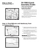


1. Lay the wood table (A) upside down on oor or bench.
2. Position legs (B) in corner as shown in Figure 7. The vertical wall of
the angle plate on the leg should be against the end wood wall (C) of
the table.
3. Carefully drill through the holes in the vertical angle plate holes and
through the wood rail of the table with a ¼” drill. Insert the 10-32 x
1-1/4” (180) with #10 washer (179) through the table end rail and
the leg vertical angle. Feed the #10-32 nuts (181) onto the screws,
against vertical angles and tighten.
4. Fasten the legs to the table board with (8) #8 x 3/4” self tapping
screws (182) (D).
5. Loosely assemble three 5/16-18 x 7/8” screws with spring washer, 3
washers and nuts (16, 58, 193) (F) into the three holes in the side of
the extension wings as shown. See Figure 8.
6. Carefully lower the slotted steel angle table bracket (G) down onto the
screws on the extension wing. Tighten the screws after the wood table
is leveled with the extension wing.
7. Using the rail alignment gauge (H) adjust the feet in the legs (I) so
the top of the table is at the proper distance from the rail.
8. Drill ¼ inch holes through the rail holes (J) into the wood table on the
front and back rails. See Figure 9.
9. Fasten wood table to rails with 1/4 - 20 x 1 1/2” at head screws for
the front rail and 1/4 -20 x 1-1/2” hex head screws for the rear rail,
at washers, and nuts (183,184,185,186) being careful to place the
washers between the nut and the wood rail, aligning rail to table and
saw top using set-up gauge (H).
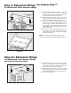
1. Attach the fence guide to the front rail using four (for 30” versions)
or six (for 52” versions) ¼-20 x ½” hex button head screws
through the holes (B) on the bottom side of the front rail.
2. Align the two holes in the power control box bracket with the holes
underneath the front rail shown in Figure 14 (C), located on the
left side of the saw. Secure the power control box to the front rail
using two ¼-20 x ½” button head screws.
Step 5: Wood Extension Table
52”rip capacity models only
Step 6: Fence Guide and
Power Control Box
- Use Hardware Bag “E”
- Use Hardware Bag “F”
FIGURE 14
FIGURE 13
FIGURE 10
FIGURE 11
FIGURE 12
G
F
FENCE GUIDE