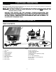
(Models 36-649, 36-675, 36-678, 36-679) MODEL 36-679 SHOWN PART NO. 912857 - 8-23-04 Copyright © 2004 Delta Machinery To learn more about DELTA MACHINERY visit our website at: www.deltamachinery.com. For Parts, Service, Warranty or other Assistance, please call 1-800-223-7278 (In Canada call 1-800-463-3582).
TABLE OF CONTENTS IMPORTANT SAFETY INSTRUCTIONS . . . . . . . . . . . . . . . . . . . . . . . . . . . . . . . . . . . . . . . . . . . . . . . . . . . . . . . . . . .2 SAFETY GUIDELINES . . . . . . . . . . . . . . . . . . . . . . . . . . . . . . . . . . . . . . . . . . . . . . . . . . . . . . . . . . . . . . . . . . . . . . . .3 GENERAL SAFETY RULES . . . . . . . . . . . . . . . . . . . . . . . . . . . . . . . . . . . . . . . . . . . . . . . . . . . . . . . . . . . . . . . . . . . .
SAFETY GUIDELINES - DEFINITIONS It is important for you to read and understand this manual. The information it contains relates to protecting YOUR SAFETY and PREVENTING PROBLEMS. The symbols below are used to help you recognize this information. Indicates an imminently hazardous situation which, if not avoided, will result in death or serious injury. Indicates a potentially hazardous situation which, if not avoided, could result in death or serious injury.
GENERAL SAFETY RULES READ AND UNDERSTAND ALL WARNINGS AND OPERATING INSTRUCTIONS BEFORE USING THIS EQUIPMENT. Failure to follow all instructions listed below, may result in electric shock, fire, and/or serious personal injury or property damage. IMPORTANT SAFETY INSTRUCTIONS 13. USE RECOMMENDED ACCESSORIES. The use of accessories and attachments not recommended by Delta may cause damage to the machine or injury to the user. 14. USE THE PROPER EXTENSION CORD.
ADDITIONAL SAFETY RULES FOR TABLE SAWS FAILURE TO FOLLOW THESE RULES MAY RESULT IN SERIOUS PERSONAL INJURY. 1. DO NOT OPERATE THIS MACHINE until it is assembled and installed according to the instructions. 2. OBTAIN ADVICE FROM YOUR SUPERVISOR, instructor, or another qualified person if you are not familiar with the operation of this machine. 3. 11. HOLD THE WORKPIECE FIRMLY against the miter gauge or fence. FOLLOW ALL WIRING CODES and recommended electrical connections. 4.
POWER CONNECTIONS A separate electrical circuit should be used for your machines. This circuit should not be less than #12 wire and should be protected with a 20 Amp time lag fuse. If an extension cord is used, use only 3-wire extension cords which have 3prong grounding type plugs and matching receptacle which will accept the machine’s plug.
3. 240 VOLT SINGLE PHASE OPERATION: GROUNDED OUTLET BOX The motor supplied with your saw is a dual voltage, 120/240 volt motor. If it is desired to operate your saw at 240 volts, single phase, it is necessary to reconnect the motor leads in the motor junction box by following the in-structions given on the motor nameplate. CURRENT CARRYING PRONGS MAKE SURE MOTOR IS DISCONNECTED FROM POWER SOURCE BEFORE RECONNECTING MOTOR LEADS.
FUNCTIONAL DESCRIPTION FOREWORD Delta Models 36-649, 36-675, 36-678 and 36-679 are 10" contractor saws. The saws have a powerful 1½ HP induction motor which can handle tough cutting operations. A RIP FENCE ASSEMBLY IS NOT PACKAGED WITH THE PRODUCT. YOU MUST INSTALL AND USE A RIP FENCE SYSTEM FOR RIPPING OPERATIONS. SEE THE SECTION “ACCESSORIES” FOR AVAILABLE FENCE SYSTEMS. NOTICE: THE PHOTO ON THE MANUAL COVER ILLUSTRATES THE CURRENT PRODUCTION MODEL.
EXTENSION WINGS MODEL 36-649 2 SHEET METAL EXTENSION WINGS MODEL 36-678 1 CAST IRON EXTENSION WING Fig. 3 STAND PARTS 1 2 3 4 5 Fig. 4 1. 2. 3. 4. 5.
HARDWARE 1 2 8 14 20 9 15 21 3 10 4 11 5 12 6 13 22 16 23 17 24 18 25 19 26 7 27 Fig. 5 1. 2. 3. 4. 5. 6. 7. 8. 9. 10. 11. 12. 13. 14.
FOR YOUR OWN SAFETY, DO NOT CONNECT THE MACHINE TO THE POWER SOURCE UNTIL THE MACHINE IS COMPLETELY ASSEMBLED AND YOU READ AND UNDERSTAND THE ENTIRE INSTRUCTION MANUAL. B STAND LEGS 1. Assemble the longer bottom bracket (A) Fig. 6, to the inside of two table legs (B) as shown. Align the holes in the longer bottom bracket (A) Fig. 6, with the holes in the table legs (B). Insert a 5/16-18x5/8" carriage bolt through the holes in the leg (B) and the hole in the longer bottom bracket (B).
4. WITH A MINIMUM OF TWO PEOPLE, CAREFULLY TURN THE SAW AND STAND UPRIGHT AS SHOWN IN FIG. 10. Carefully push down on the top of the saw until the stand legs adapt to the floor surface. Make sure the table top is level and firmly tighten all stand mounting hardware. Fig. 10 BLADE TILTING AND RAISING HANDWHEEL 1. Place blade tilting handwheel (A) Fig. 11, onto shaft (B). Make certain slot (C) in handwheel is engaged with roll pin (D) on the shaft. Place a 10mm flat washer (D) onto shaft (B) Fig. 11.
INSTALLING SWITCH AND MOTOR CORD B C 1. Insert switch cord (A) Fig. 13, and motor cord (B) of the switch assembly into the opening (C) under saw table as shown, and into the inside of the saw cabinet Fig. 14. A Fig. 13 B C A D E Fig. 14 2. Insert switch cord (A) Fig. 14, and motor cord (B) into clamps (D) and loosely fasten both cords (A) and (B) Fig. 15, to the saw cabinet by turning screws (E) Fig. 14, clockwise. NOTE: Cords will be adjusted later. Place switch on top of the saw table at this time.
MOTOR TO MOTOR MOUNTING PLATE DISCONNECT MACHINE FROM POWER SOURCE. Assemble motor (A) to motor mounting plate (B) as shown in Fig. 16. Align the four mounting holes in the motor with the four holes in the mounting plate. Insert a 5/1618x3/4" carriage bolt (C), through the hole in motor and then through the hole in the motor mounting plate, place a 5/16" flat washer (D), then a 5/16" external tooth washer (E) onto the carriage head bolt, and fasten with a 5/16-18 hex nut (F).
MOTOR PULLEY, PULLEY GUARD, AND DRIVE BELT 1. DISCONNECT MACHINE FROM POWER SOURCE. C 2. Remove the motor shaft key that is taped to the motor. A 3. Insert key (A) Fig. 20, in the keyway on the motor shaft. Assemble motor pulley (B) on motor shaft as shown, with the hub of the pulley out. Tighten set screw (C) against key (A) in motor shaft. B Fig. 20 4. Slide the belt and pulley guard bracket (G) Fig. 22, between the motor plate (A) and motor mounting plate (C), as shown. D 5.
9. IMMEDIATELY AFTER ASSEMBLING THE BELT, RAISE THE SAW BLADE TO ITS MAXIMUM HEIGHT AND TILT THE SAW BLADE TO 45 DEGREES. USING A STRAIGHT EDGE (L) FIG. 25, CHECK TO SEE IF THE MOTOR END (J) FIG. 25, IS BELOW THE TOP OF THE TABLE SURFACE (K). IF THE MOTOR END (J) IS ABOVE THE TOP OF THE TABLE SURFACE, THE MOTOR MUST BE MOVED TO THE LEFT UNTIL YOU ARE CERTAIN THE TOP (J) OF THE MOTOR IS BELOW THE TOP OF THE TABLE SURFACE. THEN RE-ALIGN THE MOTOR PULLEY TO THE ARBOR PULLEY. K L J Fig. 25 10.
BLADE GUARD AND SPLITTER ASSEMBLY AND ALIGNMENT 1. B A DISCONNECT MACHINE FROM POWER SOURCE. 2. Fasten the rear splitter mounting bracket (A) Fig. 29, to the rear trunnion. Align the two holes in the rear splitter mounting bracket with the two holes in the trunnion.
8. Assemble the blade guard and splitter assembly (G) Fig. 33, between the large washer (C) and the splitter bracket and tighten screw (H) with wrench supplied. G C H Fig. 33 L G J 9. Fasten the rear of the blade guard and splitter bracket assembly (G) Fig. 34, to the rear splitter mounting bracket. Align the hole in the blade guard and splitter bracket with the hole in the rear splitter mounting bracket.
11. Using a straight edge, check to see if the saw blade is aligned with the rear of the splitter (G), as shown in Fig. 37. If alignment is necessary, loosen the screws (A) Fig. 37, align splitter (G) with the saw blade, and tighten two screws (A). G A 12. Lower saw blade and install table insert (P) Fig. 38, in the saw table as shown. THE TABLE INSERT SHOULD BE LEVEL WITH THE TABLE SURFACE. IF AN ADJUSTMENT IS NECESSARY, SEE THE SECTION “ADJUSTING TABLE INSERT”.
OPERATION OPERATIONAL CONTROLS AND ADJUSTMENTS A B A Fig. 41 Fig. 42 STARTING AND STOPPING SAW 1. The on/off switch is located underneath the switch shield (A) Fig. 41. To turn the saw “ON”, move switch trigger (B) to the up position. 2. To turn the saw “OFF”, push down on switch shield (A) Fig. 42. LOCKING SWITCH IN THE “OFF” POSITION IMPORTANT: When the machine is not in use, the switch should be locked in the “OFF” position to prevent unauthorized use, using a padlock (C) Fig.
RAISING AND LOWERING BLADE To raise the saw blade, loosen lock knob (A) Fig. 44, and turn the blade raising handwheel (B) clockwise. When the blade is at the desired height, tighten lock knob (A). To lower the blade, loosen lock knob (A) Fig. 44, and turn the handwheel (B) counterclockwise. NOTE: One full turn of the handwheel will change blade height approximately 1/4". A C B D TILTING THE BLADE Fig. 44 To tilt the saw blade for bevel cutting, loosen lock knob (C) Fig.
MITER GAGE OPERATION AND ADJUSTMENT B Insert the miter gage bar (B) Fig. 47, into the miter gage slot. Insert the metal stud on the bottom of the miter gage body (C) Fig. 47, into the non tapped hole in the miter gage bar. Place a 21/64" flat washer (D) Fig. 47, onto the miter gage handle (A). Insert the threaded end of the miter gage handle (A) Fig. 47 through the slot (E) on the miter gage body and thread the handle into the miter gage bar (B).
CHANGING THE SAW BLADE USE ONLY 10" DIAMETER BLADES WITH 5/8" ARBOR HOLES, RATED AT 3450 RPM OR HIGHER. 1. DISCONNECT MACHINE FROM POWER SOURCE. 2. NOTE: Two 7/8" wrenches are supplied with the saw for changing the saw blade: a box end wrench (A) Fig. 51, and open end wrench (B). C A 3. Remove table insert (C) Fig. 68, and raise saw blade to its maximum height. B 4. Place the open end wrench (B) Fig.
MACHINE USE Common sawing operations include ripping and crosscutting plus a few other standard operations of a fundamental nature. As with all power machines, there is a certain amount of hazard involved with the operation and use of the machine. Using the machine with the respect and caution demanded as far as safety precautions are concerned, will considerably lessen the possibility of personal injury.
RIPPING Ripping is cutting lengthwise through a board, (Fig. 55). NOTE: Be sure the material to be cut is seasoned, dry and flat. The rip fence (A) is used to position and guide the work. One edge of the work rides against the rip fence while the flat side of the board rests on the table. Since the work is pushed along the fence, it must have a straight edge and make solid contact with the table. A THE SAW BLADE GUARD MUST BE USED.
ACCESSORY MOULDING CUTTERHEAD USING MOULDING CUTTERHEAD Moulding is cutting a shape on the edge or face of the work. Cutting mouldings with a moulding cutterhead is a fast, safe and clean operation.The many different knife shapes available make it possible for the operator to produce almost any kind of mouldings, such as various styles of corner moulds, picture frames, table edges, etc. The moulding head consists of a cutterhead in which can be mounted various shapes of steel knives, (Fig. 58).
SPECIAL ATTENTION SHOULD BE GIVEN THE GRAIN DIRECTION. MAKE ALL CUTS IN THE SAME DIRECTION AS THE GRAIN WHENEVER POSSIBLE. C A LW AY S I N S TA L L B L A D E G U A R D AFTER OPERATION IS COMPLETE. Fig. 61 USING ACCESSORY DADO HEAD THE BLADE GUARD AND SPLITTER ASSEMBLY CANNOT BE USED WHEN DADOING OR MOULDING. IT MUST BE REMOVED OR SWUNG TO THE REAR OF THE SAW AS DESCRIBED IN “USING ACCESSORY MOULDING CUTTERHEAD” SECTION. AUXILIARY JIGS, FIXTURES, PUSH STICKS AND FEATHER BOARDS SHOULD BE USED. 1.
USING AUXILIARY WOOD FACING ON RIP FENCE It is necessary when performing special operations such as when using the moulding cutterhead to add wood facing (A) Fig. 66, to one or both sides of the rip fence. Depending on the fence, the wood facing is attached to the fence either with wood screws through holes drilled in the fence (as shown in Fig. 66) or with two clamps. For most work, 3/4" stock is suitable, although an occasional job may require one-inch facing. A Fig. 66 CONSTRUCTING A FEATHERBOARD Fig.
CONSTRUCTING A PUSH STICK 1/2" SQUARES CUT OFF HERE TO PUSH 1/2" WOOD CUT OFF HERE TO PUSH 1/4" WOOD NOTCH TO HELP PREVENT HAND FROM SLIPPING MAKE FROM 1/2" OR 3/4" WOOD OR THICKNESS LESS THAN WIDTH OF MATERIAL TO BE CUT PUSH STICK When ripping work less than 4 inches wide, a push stick should be used to complete the feed and could easily be made from scrap material by following the pattern shown in Fig. 69. Fig. 69 TROUBLESHOOTING For assistance with your machine, visit our website at www.
MAINTENANCE KEEP MACHINE CLEAN LUBRICATION Periodically blow out all air passages with dry compressed air. All plastic parts should be cleaned with a soft damp cloth. NEVER use solvents to clean plastic parts. They could possibly dissolve or otherwise damage the material. Apply household floor paste wax to the machine table and extension table or other work surface weekly.
ACCESSORIES A complete line of accessories is available from your Delta Supplier, Porter-Cable • Delta Factory Service Centers, and Delta Authorized Service Stations. Please visit our Web Site www.deltamachinery.com for a catalog or for the name of your nearest supplier. Since accessories other than those offered by Delta have not been tested with this product, use of such accessories could be hazardous. For safest operation, only Delta recommended accessories should be used with this product.
PORTER-CABLE • DELTA SERVICE CENTERS (CENTROS DE SERVICIO DE PORTER-CABLE • DELTA) Parts and Repair Service for Porter-Cable • Delta Machinery are Available at These Locations (Obtenga Refaccion de Partes o Servicio para su Herramienta en los Siguientes Centros de Porter-Cable • Delta) ARIZONA Tempe 85282 (Phoenix) 2400 West Southern Avenue Suite 105 Phone: (602) 437-1200 Fax: (602) 437-2200 CALIFORNIA Ontario 91761 (Los Angeles) 3949A East Guasti Road Phone: (909) 390-5555 Fax: (909) 390-5554 Tampa 3360