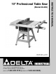
(Model 36-650) PART NO. 902113 - 11-22-02 Copyright © 2002 Delta Machinery To learn more about DELTA MACHINERY visit our website at: www.deltamachinery.com. For Parts, Service, Warranty or other Assistance, please call 1-800-223-7278 (In Canada call 1-800-463-3582).
SAFETY GUIDELINES / DEFINITIONS This manual contains information that is important for you to know and understand. This information relates to protecting YOUR SAFETY and PREVENTING EQUIPMENT PROBLEMS. To help you recognize this information, we use the symbols to the right. Please read the manual and pay attention to these sections. Indicates an imminently hazardous situation which, if not avoided, will result in death or serious injury.
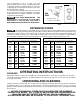
17. REDUCE THE RISK OF UNINTENTIONAL STARTING. Make sure switch is in “OFF” position before plugging in power cord. In the event of a power failure, move switch to the “OFF” position. 18. NEVER STAND ON TOOL. Serious injury could occur if the tool is tipped or if the cutting tool is accidentally contacted. 19. CHECK DAMAGED PARTS.
POWER CONNECTIONS A separate electrical circuit should be used for your machines. This circuit should not be less than #12 wire and should be protected with a 20 Amp time lag fuse. If an extension cord is used, use only 3-wire extension cords which have 3prong grounding type plugs and matching receptacle which will accept the machine’s plug.
saw as illustrated in Fig. C. Contact your local Authorized Delta Service Center or qualified electrician for proper procedures to install the plug. The saw must comply with all local and national electrical codes after the 240 volt plug is installed. The saw with a 240 volt plug should only be connected to an outlet having the same configuration as the plug illustrated in Fig. C. No adapter is available or should be used with the 240 Volt plug.
10" PROFESSIONAL TABLE SAW PARTS 1 3 4 5 2 8 9 10 12 13 6 7 11 20 15 14 17 16 18 19 Fig. 2 1. 2. 3. 4. 5. 6. 7. 8. 9. 10. Table Saw Extension Wing (2) Motor Pulley Guard Plate Switch Assembly Lock Knob (2) Handwheel (2) Miter Gage Handle Motor Plate Motor Pulley 11. 12. 13. 14. 15. 16. 17. 18. 19. 20.
STAND PARTS 1 2 3 4 5 Fig. 4 1. 2. 3. 4. 5. Leg (4) Bracket 24" Long (2) Bracket 21" Long (2) Top Bracket (1) Plastic Foot (4) HARDWARE 1 9 15 21 2 10 16 22 3 11 17 23 4 12 18 24 5 13 19 25 6 14 20 26 7 27 8 28 Fig. 5 1. 2. 3. 4. 5. 6. 7. 8. 9. 10. 11. 12. 13. 14.
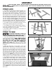
ASSEMBLY FOR YOUR OWN SAFETY, DO NOT CONNECT THE MACHINE TO THE POWER SOURCE UNTIL THE MACHINE IS COMPLETELY ASSEMBLED AND YOU READ AND UNDERSTAND THE ENTIRE INSTRUCTION MANUAL. B STAND LEGS 1. Assemble the longer bottom bracket (A) Fig. 6, to the inside of two table legs (B) as shown. Align the holes in the longer bottom bracket (A) Fig. 6, with the holes in the table legs (B).
4. WITH A MINIMUM OF TWO PEOPLE, CAREFULLY TURN THE SAW AND STAND UPRIGHT AS SHOWN IN FIG. 10. Carefully push down on the top of the saw until the stand legs adapt to the floor surface and firmly tighten all stand mounting hardware. Fig. 10 BLADE TILTING AND RAISING HANDWHEEL 1. Place blade tilting handwheel (A) Fig. 11, onto shaft (B). Make certain slot (C) in handwheel is engaged with roll pin (D) on the shaft. Place a 10mm flat washer onto shaft (B) Fig. 11. Thread locking knob (E) Fig.
INSTALLING SWITCH AND MOTOR CORD B C 1. Insert switch cord (A) Fig. 13, and motor cord (B) of the switch assembly into the opening (C) under saw table as shown, and into the inside of the saw cabinet Fig. 14. A Fig. 13 B C A D E Fig. 14 2. Insert switch cord (A) Fig. 14, and motor cord (B) into clamps (D) and loosely fasten both cords (A) and (B) Fig. 15, to the saw cabinet by turning screws (E) Fig. 14, clockwise. NOTE: Cords will be adjusted later. Place switch on top of the saw table at this time.
MOTOR TO MOTOR MOUNTING PLATE DISCONNECT MACHINE FROM POWER SOURCE. B Assemble motor (A) to motor mounting plate (B) as shown in Fig. 16. Align the four mounting holes in the motor with the four holes in the mounting plate.
MOTOR PULLEY, PULLEY GUARD, AND DRIVE BELT C DISCONNECT MACHINE FROM POWER SOURCE. A 1. Remove the motor shaft key that is taped to the motor. B 2. Insert key (A) Fig. 20, in the keyway on the motor shaft. Assemble motor pulley (B) on motor shaft as shown, with the hub of the pulley out. Tighten set screw (C) against key (A) in motor shaft. Fig. 20 3. Slide the belt and pulley guard bracket (G) Fig. 22, between the motor plate (A) and motor mounting plate (C), as shown. D 4.
8. IMMEDIATELY AFTER ASSEMBLING THE BELT, RAISE THE SAW BLADE TO ITS MAXIMUM HEIGHT AND TILT THE SAW BLADE TO 45 DEGREES. USING A STRAIGHT EDGE (L) FIG. 25, CHECK TO SEE IF THE MOTOR END (J) FIG. 25, IS BELOW THE TOP OF THE TABLE SURFACE (K). IF THE MOTOR END (J) IS ABOVE THE TOP OF THE TABLE SURFACE, THE MOTOR MUST BE MOVED TO THE LEFT UNTIL YOU ARE CERTAIN THE TOP (J) OF THE MOTOR IS BELOW THE TOP OF THE TABLE SURFACE. THEN RE-ALIGN THE MOTOR PULLEY TO THE ARBOR PULLEY. K L J Fig. 25 9.
BLADE GUARD AND SPLITTER ASSEMBLY B A DISCONNECT MACHINE FROM POWER SOURCE. 1. Fasten the rear splitter mounting bracket (A) Fig. 29, to the rear trunnion. Align the two holes in the rear splitter mounting bracket with the two holes in the trunnion. Place a 1/4" lock washer onto a 1/4-20x3/4" hex head screw, place a 1/4" flat washer onto the hex head screw, insert the hex head screw through the hole in the rear splitter mounting bracket and thread the hex head screw into the rear trunnion.
7. Assemble the blade guard and splitter assembly (G) Fig. 33, between the large washer (C) and the splitter bracket and tighten screw (H) with wrench supplied. G C H Fig. 33 L G J 8. Fasten the rear of the blade guard and splitter bracket assembly (G) Fig. 34, to the rear splitter mounting bracket. Align the hole in the blade guard and splitter bracket with the hole in the rear splitter mounting bracket.
10. Using a straight edge, check to see if the saw blade is aligned with the rear of the splitter (G), as shown in Fig. 37. If alignment is necessary, loosen the screws (A) Fig. 37, align splitter (G) with the saw blade, and tighten two screws (A). G A 11. Lower saw blade and install table insert (P) Fig. 38, in the saw table as shown. THE TABLE INSERT SHOULD BE LEVEL WITH THE TABLE SURFACE. IF AN ADJUSTMENT IS NECESSARY, SEE THE SECTION “ADJUSTING TABLE INSERT”. Fig.
GUIDE RAILS AND SWITCH ASSEMBLY 1. Loosely assemble front guide rail (A) Fig. 40, to the front of the saw table. Align the two holes (B) and (C) with the two holes in the saw table. Insert a 3/8-16x11/2" flat head screw (F) Fig. 40, through holes (B) and (C) in the front guide rail (A) and the holes in the front of the saw table. Place hole in switch bracket (E) Fig. 40, on screw (B) located behind the inner lip of the saw table.
RIP FENCE TO GUIDE RAILS B 1. Insert end cap (A) Fig. 45, into back of rip fence (B). A 2. With the fence handle (A) Fig. 46, in the raised position, place the rip fence (B) onto the rear guide rail (C) so the hooked end (D) Fig. 45, fits over the top ledge of the guide rail as shown. D C Fig. 45 3. Lower the front of rip fence (B) Fig. 46, onto the front guide rail (L). B 4. Lock the rip fence (B) Fig. 46, on the guide rails by pushing down handle (A). C L 5. Slide rip fence (B) Fig.
OPERATING CONTROLS AND ADJUSTMENTS STARTING AND STOPPING SAW 1. The on/off switch is located underneath the switch shield (A) Fig. 54. To turn the saw “ON,” move switch trigger (B) to the up position. A B Fig. 54 2. To turn the saw “OFF,” push down on switch shield (A) Fig. 55. A Fig. 55 LOCKING SWITCH IN THE “OFF” POSITION IMPORTANT: When the tool is not in use, the switch (B) Fig.56, should be locked in the OFF position using a padlock (C), with a 3/16" diameter shackle to prevent unauthorized use.
RAISING AND LOWERING THE BLADE To raise the saw blade, loosen lock knob (A) Fig. 58, and turn the blade raising handwheel (B) clockwise. When the blade is at the desired height, tighten lock knob (A). To lower the blade, loosen lock knob (A) Fig. 58, and turn the handwheel (B) counterclockwise. NOTE: One full turn of the handwheel will change blade height approximately 1/4". A C B D Fig. 58 TILTING THE BLADE To tilt the saw blade for bevel cutting, loosen lock knob (C) Fig.
BACKLASH ADJUSTMENTS FOR BLADE RAISING AND BLADE TILTING MECHANISMS C D If any play is detected in the blade raising or blade tilting mechanisms, the following adjustments should be made. DISCONNECT MACHINE FROM POWER SOURCE. 1. NOTE: The machine has been turned upside down and the blade removed for clarity and safety. 2. Adjusting blade raising mechanism - Loosen locknut (A) Fig. 61, and turn eccentric sleeve (B) until all play is removed in mechanism, then tighten locknut (A). 3.
5. Depending on the type of saw blade being used, the cursor (D) Fig. 64, may need adjustment to compensate for the blade thickness.To adjust the cursor, make a test cut on a piece of lumber and measure the finished cut, or you can place the rip fence against the blade as shown earlier in the manual. If a minor adjustment is necessary, loosen two screws (E) Fig. 64, and move the cursor (D) as necessary. D E E Fig. 64 MITER GAGE OPERATION AND ADJUSTMENT B A Insert the miter gage bar (B) Fig.
ADJUSTING TABLE INSERT B DISCONNECT MACHINE FROM POWER SOURCE. Place a straight edge across the table at both ends of the table insert as shown in Fig. 68. The table insert (A) should always be level with the table. If an adjustment is necessary, turn the adjusting screws (B), as needed. Four adjusting screws (B) are supplied in the table insert. The table insert is equipped with a finger hole (C) for easy removal. A C B Fig.
OPERATIONS Common sawing operations include ripping and crosscutting plus a few other standard operations of a fundamental nature. As with all power tools, there is a certain amount of hazard involved with the operation and use of the machine. Using the machine with the respect and caution demanded as far as safety precautions are concerned, will considerably lessen the possibility of personal injury.
RIPPING Ripping is the operation of making a lengthwise cut through a board, as shown in Fig. 82, and the rip fence (A) is used to position and guide the work. One edge of the work rides against the rip fence while the flat side of the board rests on the table. Since the work is pushed along the fence, it must have a straight edge and make solid contact with the table. The saw guard must be used.
For certain cutting operations such as dadoing and moulding where you are not cutting completely through the workpiece, the blade guard and splitter assembly cannot be used. Loosen screws (G) and (H) Fig. 85. Lift up and swing blade guard and splitter assembly (W) Fig. 86, to the rear of the saw, and then tighten screws (G) and (H). H Always return and fasten the blade guard and splitter assembly to its proper operating position for normal thru-sawing operations. G The moulding cutterhead (A) Fig.
USING ACCESSORY DADO HEAD THE BLADE GUARD AND SPLITTER ASSEMBLY CANNOT BE USED WHEN DADOING OR MOULDING AND MUST BE REMOVED OR SWUNG TO THE REAR OF THE SAW. Dadoing is cutting a rabbet or wide groove into the work. Most dado head sets are made up of two outside saws and four or five inside cutters, as shown in Fig. 89. Various combinations of saws and cutters are used to cut grooves from 1/8" to 13/16" for use in shelving, making joints, tenoning, grooving, etc.
USING AUXILIARY WOOD FACING ON RIP FENCE B A It is necessary when performing special operations such as moulding to add wood facing (A) Fig. 94, to one or both sides of the rip fence, as shown. The wood facing is attached to the fence with wood screws (B), countersunk and assembled through the holes provided in the fence. 3/4 inch stock is suitable for most work although an occasional job may require 1 inch facing.
CONSTRUCTING A PUSH STICK 29 1/2" SQUARES CUT OFF HERE TO PUSH 1/2" WOOD CUT OFF HERE TO PUSH 1/4" WOOD NOTCH TO HELP PREVENT HAND FROM SLIPPING MAKE FROM 1/2" OR 3/4" WOOD OR THICKNESS LESS THAN WIDTH OF MAT’L. TO BE CUT PUSH STICK When ripping work less than 4 inches wide, a push stick should be used to complete the feed and could easily be made from scrap material by following the pattern shown.
ACCESSORIES A complete line of accessories is available from your Delta Supplier, Porter-Cable • Delta Factory Service Centers, and Delta Authorized Service Stations. Please visit our Web Site www.deltamachinery.com for a catalog or for the name of your nearest supplier. Since accessories other than those offered by Delta have not been tested with this product, use of such accessories could be hazardous. For safest operation, only Delta recommended accessories should be used with this product.
NOTES 31
PORTER-CABLE • DELTA SERVICE CENTERS (CENTROS DE SERVICIO DE PORTER-CABLE • DELTA) Parts and Repair Service for Porter-Cable • Delta Machinery are Available at These Locations (Obtenga Refaccion de Partes o Servicio para su Herramienta en los Siguientes Centros de Porter-Cable • Delta) ARIZONA Tempe 85282 (Phoenix) 2400 West Southern Avenue Suite 105 Phone: (602) 437-1200 Fax: (602) 437-2200 CALIFORNIA Ontario 91761 (Los Angeles) 3949A East Guasti Road Phone: (909) 390-5555 Fax: (909) 390-5554 San Leandro