
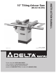
Instruction manual

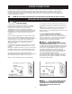


7
Figure 5
The following saw parts require assembly. Please be sure all of the listed parts are included before starting assembly.
Fig. 5
1. Right Extension Wing with Hex Screws (3),
Flat Washers (3), and Lock Washers (3)
2. Switch Assembly with Hex Screws (2) and
Square Nuts (2)
3. Splitter/Guard Assembly with Hex Head
Screw (1), Special Washer (1), and Carriage
Head Bolt (1) with Flatwasher (1), Lock
Washer (1), Hex Nut (1)
4. Dust Port with Pan Head Screws (4) and Hex
Nuts (4)
5. Miter Gage Assembly
6. Table Insert with Button Head Screw (1)
7. Depth Stop Assembly with Special Washer
(1), Socket Head Cap Screw (1), Lock Nut
(1), Hex Socket Screws (2), Hex Nuts (2), and
Lock Knob (1).
8. Cross Cut Fence
9. Blade with Blade Flange (1) and Blade Hex
Nut (1)
10. Leveling Pads (4)
11. Wrench Hook with Self Tapping Pan Head
Screws (2)
12. Miter Gage Holder with Self Tapping Pan
Head Screws (4)
13. Fence Holder Brackets (2) with Self Tapping
Pan Head Screws (4)
14. Blade Wrenches (2)
15. Left Extension Wing with Hex Screws (3),
Lock Washers (3), and Flat Washers (3)
16. Splitter Mounting Bracket with Hex Head
Screws (2), Lock Washers (2) and Flat
Washers (2)
17. Drive Belt
18. Handwheel (2) with Locking Knobs(2)