
Use and Care Manual


10
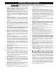
SECURING SAW TO A PERMANENT
LOCATION
If you desire, you can attach your saw permanently to the
oor by drilling holes at four locations provided in the base
of the saw (two are shown at (A) Fig. 4).
RISK OF INJURY FROM LIFTING. Serious
injury can result from attempting to lift too heavy an object.
The machine is too heavy to be lifted by one person.
Obtain assistance from others before lifting.
PINCH HAZARD. Be sure not place toes or
ngers underneath the base of the Unisaw while moving.
Lift the saw from underneath the table, before assembly,
or the wings and extension table after assembly.
EXTENSION WINGS
NOTE: Be sure to remove switch and switch mounting
hardware from its shipping location. Switch will be
mounted to extension wing.
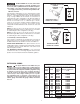
1. Align the three holes in the one extension wing with
the three holes in the side of the saw table. Assembled
wing shown in Fig. 7.
2. Place an M12 lockwasher on an M12 hex head screw.
Insert the screw through the hole in the extension wing
and thread the screw into the threaded hole in the side
of the table. FINGER TIGHTEN ONLY. Repeat this
process for the two remaining holes in the extension
wing and saw table.
NOTE: Ensure that the front edge of the wing is ush with
or slightly behind the front edge of the table.
3. Use a straight edge to level the extension wing with
the saw table before tightening the three bolts (H) Fig.
7. Use an 18 mm open-end wrench and start with a
bolt on one side.
4. Align the table and wing making sure they are level
and tighten that side bolt. Move to the middle bolt and
follow the same procedure. Finish with the bolt on the
other end.
5. Place the other extension wing on the other side of the
saw in the same manner.
ASSEMBLY
ASSEMBLY TOOLS REQUIRED
ASSEMBLY TIME ESTIMATE
Assembly for this machine takes approximately 2 hours.
To reduce the risk of injury, turn unit off and disconnect it from power source before installing and
removing accessories, before adjusting or when making repairs. An accidental start-up can cause injury.
• 18 mm and 1/2" open-end or socket wrench (not
supplied)
• 3/16"hex wrench (not supplied)
FIG. 7
H
A
FIG. 4