(Model 37-070) PART NO. 901609 (013) Copyright © 2001 Delta Machinery To learn more about DELTA MACHINERY visit our website at: www.deltamachinery.com. For Parts, Service, Warranty or other Assistance, please call ESPAÑOL: PÁGINA 21 1-800-223-7278 (In Canada call 1-800-463-3582).
SAFETY RULES Woodworking can be dangerous if safe and proper operating procedures are not followed. As with all machinery, there are certain hazards involved with the operation of the product. Using the machine with respect and caution will considerably lessen the possibility of personal injury. However, if normal safety precautions are overlooked or ignored, personal injury to the operator may result.
ADDITIONAL SAFETY RULES FOR JOINTERS 1. DO NOT OPERATE the tool until it is completely assembled and installed according to the instructions. 15. NEVER make jointing or planing cuts deeper than 1/8 inch. On cuts more than 1-1/2 inches wide, adjust depth of cut to 1/16 inch or less to avoid overloading machine and to minimize chance of kick-back (work thrown back toward you). 2.
CONNECTING TOOL TO POWER SOURCE POWER CONNECTIONS A separate electrical circuit should be used for your tools. This circuit should not be less than #12 wire and should be protected with a 20 Amp time lag fuse. If an extension cord is used, use only 3-wire extension cords which have 3prong grounding type plugs and 3-hole receptacles which accept the tool’s plug.
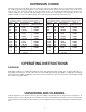
EXTENSION CORDS Use proper extension cords. Make sure your extension cord is in good condition and is a 3-wire extension cord which has a 3-prong grounding type plug and a 3-hole receptacle which will accept the tool’s plug. When using an extension cord, be sure to use one heavy enough to carry the current of the tool. An undersized cord will cause a drop in line voltage, resulting in loss of power and overheating. Fig. DD, shows the correct gauge to use depending on the cord length.
DEFINITIONS OF JOINTING AND PLANING OPERATIONS Fig. 2 Fig. 3 1. JOINTING OPERATIONS – Jointing cuts or edge jointing are made to square an edge of a workpiece. The workpiece is positioned on the jointer with the narrow edge of the workpiece on the infeed table and the major flat surface of the workpiece against the fence, as shown in Fig. 2. The workpiece is moved from the infeed table, across the cutterhead to the outfeed table. 2.
11 13 6 4 5 1 8 10 16 7 14 15 9 3 12 2 Fig.
ASSEMBLY INSTRUCTIONS WARNING: FOR YOUR OWN SAFETY, DO NOT CONNECT THE TOOL TO THE POWER SOURCE UNTIL THE MACHINE IS COMPLETELY ASSEMBLED AND YOU HAVE READ AND UNDERSTAND THE ENTIRE OWNERS MANUAL. A ASSEMBLING FENCE 1. Assemble the fence mounting bracket (A) Fig. 5, to the jointer base using the four 5/8" long socket button head screws (B) Fig. 6. Fig. 5 B B Fig. 6 D E C A 2. Assemble the fence sliding bracket (C) Fig.
3. Assemble 5/8" long socket button head screw (G) Fig. 9, to fence tilting bracket (H) and thread T-nut (J) onto threaded end of screw (G) as shown. DO NOT COMPLETELY TIGHTEN SCREW (G) AT THIS TIME. Assemble screw and T-nut to opposite end of tilting bracket in the same manner. H J G Fig. 9 4. Slide groove of fence (L) Fig. 10, over T-nuts (J) as shown. L J Fig. 10 5. Position fence (L) Fig. 11, so that rounded section (M) on bottom of fence is over cutterhead opening as shown. L M Fig. 11 6.
ASSEMBLING CUTTERHEAD GUARD A 1. Thread the two 7/16" long socket button head screws (A) Fig. 13, into the two threaded holes in front side of jointer base. DO NOT COMPLETELY TIGHTEN SCREWS (A) AT THIS TIME. Fig. 13 2. Assemble guard mounting bracket (B) Fig. 14, to the two screws (A) as shown, and tighten the two screws (A). A A B Fig. 14 A ASSEMBLING CUTTERHEAD LOCK B 1. Assemble cutterhead lock (A) Fig.
FASTENING JOINTER TO SUPPORTING SURFACE If during operation, there is any tendency for the jointer to tip over, slide or walk on the supporting surface, the jointer must be secured to the supporting surface with fasteners through the four holes, two of which are shown at (A) Fig. 20, in the jointer base. A A Fig. 20 OPERATING CONTROLS AND ADJUSTMENTS STARTING AND STOPPING JOINTER The on/off switch (A) Fig. 21, is located on the front of the jointer cabinet.
VARIABLE SPEED CONTROL Your jointer is supplied with a variable speed control knob (A) Fig. 23, that enables you to operate the machine at cutterhead speeds between 6000 and 11,000 RPM. Speed indicators of 1-2-3-4 and 5 are provided on the speed dial as shown. When the pointer (B) is pointing to 1, the cutterhead speed will be 6000 RPM; 2 – 7250 RPM; 3 – 8800 RPM; 4 – 9750 RPM; and 5 – 11,000 RPM. A C B SPEED CONTROL CHART A speed control chart (C) Fig.
3. The fence features adjustable positive stops at the most used fence positions of 90 degrees and 45 degrees to the right. To check and adjust the positive stops, proceed as follows: 4. Place a square (C) Fig. 26, on the table with one end of the square against the fence as shown. Adjust the fence until it is exactly 90 degrees to the table. C Fig. 26 5. Turn set screw (D) Fig. 27, until it contacts stop (E). D E Fig. 27 6. Using a square (C) Fig.
ADJUSTING KNIVES When it becomes necessary to adjust the knives due to replacement or wear, proceed as follows: D F A E B C Fig. 31 Fig. 30 1. DISCONNECT THE TOOL FROM THE POWER SOURCE AND REMOVE CUTTERHEAD GUARD. 2. Rotate cutterhead and loosen four screws (A) Fig. 30. NOTE: Do not overly loosen the screws (A). Loosen one half turn or only enough so knife can slide between locking plate and cutterhead. 3. Rotate cutterhead and engage cutterhead lock (B) Fig. 31, on cutterhead shaft as shown.
8. If the knives are set too high, the work will be gouged at the end of the cut, as shown in Fig. 33. MATERIAL IN-FEED TABLE OUT-FEED TABLE KNIVES SET TOO HIGH CUTTER GOUGE Fig. 33 9. As a final check, run a piece of work slowly over the knives for 6 to 8 inches. The wood should rest firmly on both tables as shown in Fig. 34, with no open spaces under the finished cut. MATERIAL OUT-FEED TABLE KNIVES AT CORRECT HEIGHT IN-FEED TABLE CUTTER Fig.
PUSH BLOCKS A set of push blocks (A) Fig. 37, is supplied with your jointer and should be used whenever possible to minimize all danger to your hands. Fig. 37, illustrates using the push blocks properly. A Fig. 37 OPERATION The following directions will give the beginner a start on jointer operations. Use scrap pieces of lumber to check the settings and to get the feel of the operations before attempting regular work. WARNING: ALWAYS USE CUTTERHEAD GUARD AND KEEP HANDS AWAY FROM CUTTERHEAD.
PLANING WARPED PIECES If the wood to be planed is dished or warped, take light cuts until the surface is flat. Avoid forcing such material down against the table; excessive pressure will spring it while passing the knives, and it will spring back and remain curved after the cut is completed. PLANING SHORT OR THIN WORK When planing short or thin pieces, always use push blocks to minimize all danger to the hands. Fig. 40, illustrates using the Push Blocks properly. Fig.
MAINTENANCE BELT REPLACEMENT When it becomes necessary to replace the belt on your jointer, proceed as follows: B 1. DISCONNECT THE TOOL FROM THE POWER SOURCE. A 2. Remove screw (A) Fig. 43, using Allen wrench supplied, and remove belt guard (B). Fig. 43 3. Loosen three screws (C) Fig. 44, to release belt tension and remove belt (D) from pulleys. B 4. Assemble new belt to the cutterhead and motor pulleys. Press down on motor pulley (E) Fig. 44, to tension belt and tighten three screws (C). C D 5.
ACCESSORIES A complete line of accessories is available from your Delta Supplier, Porter-Cable • Delta Factory Service Centers, and Delta Authorized Service Stations. Please visit our Web Site www.deltamachinery.com for a catalog or for the name of your nearest supplier. WARNING: Since accessories, other than those offered by Delta, have not been tested with this product, use of such accessories could be hazardous. For safest operation, only Delta recommended accessories should be used with this product.
NOTES 20
PORTER-CABLE DELTA SERVICE CENTERS (CENTROS DE SERVICIO DE PORTER-CABLE DELTA) Parts and Repair Service for Porter-Cable/Delta Power Tools are Available at These Locations (Obtenga Refaccion de Partes o Servicio para su Herramienta en los Siguientes Centros de Porter-Cable Delta) ARIZONA Tempe 85282 (Phoenix) 2400 West Southern Avenue Suite 105 Phone: (602) 437-1200 Fax: (602) 437-2200 CALIFORNIA Ontario 91761 (Los Angeles) 3949A East Guasti Road Phone: (909) 390-5555 Fax: (909) 390-5554 San Leandro 94577