(Model 37-285) Record this information for future reference. SERIAL NO._____________________ D ATE O F P U R C H A S E ____________ See Table of Contents for location of Serial No. D ATED 1-20-99 PA RT NO. 1347169 'Delta International Machinery Corp.
TA B L E O F C O N T E N T S SAFETY RULES ...............................................................................................................................................................3 ADDITIONAL SAFETY RULES F O R JOINTERS.............................................................................................................4 DEFINITIONS O F JOINTING & PLANING O P E R ATIONS...............................................................................................
SAFETY RULES W oodworking can be dangerous if safe and proper operating procedures are not followed. As with all machinery, there are certain hazards involved with the operation of the product. Using the machine with respect and caution will considerably lessen the possibility of personal injury. However, if normal safety precautions are overlooked or ignored, personal injury to the operator may result.
ADDITIONAL SAFETY RULES FOR JOINTERS 1. W ARNING: Do not operate the jointer until it is completely assembled and installed according to the instructions. 15. N E V E R make jointing or planing cuts deeper than 1/8 inch. On cuts more than 1-1/2 inches wide, adjust depth of cut to 1/16 inch or less to avoid overloading machine and to minimize chance of kick-back (work thrown back toward you). 2.
DEFINITIONS O F JOINTING AND PLANING O P E R ATIONS Fig. 2 Jointing Operations - Jointing cuts or edge jointing is the simplest and most common operation which can be done on the jointer and these cuts are made to square an edge of a workpiece. The fence is square with the table and the depth of cut is approximately 1/8 inch. The workpiece is positioned on the jointer with the narrow edge of the workpiece on the infeed table and the major flat surface of the workpiece against the fence, as shown in Fig. 2.
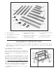
U N PACKING A N D CLEANING The 6 Motorized Jointer is shipped complete in one container. Carefully unpack the jointer,stand, and all loose items from the container. Figs. 4 and 5 illustrate the items supplied with the jointer. 1. W ARNING: For your own safety, DO NOT connect the jointer to a power source until the machine is completely assembled and you have read and understood the entire owner s manual. 2.
27 26 28 29 34 33 32 30 31 Fig. 5 26. Legs for Stand (4) 27. Two Top End Braces for Stand (10-1/2 long) 28. Two Bottom End Braces for Stand (15-1/2 long) 29. Top Front and Rear Braces for Stand (25-1/2 long) 32. 1/2 Long Carriage Bolts for Stand (32) 30. Bottom Front and Rear Braces for Stand (30-1/2 long) 33. Flat Washers for Stand (32) 34. Hex Nuts for Stand (32) 31.
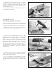
ASSEMBLING STA N D A N D D U S T C H U T E TO JOINTER M A K E C E R TAIN T H E MACHINE IS DISCONNECTED F R O M T H E P O W E R S O U R C E A N D T H AT KNIFE G U A R D (A) FIG. 13, IS POSITIONED O V E R THE C U TTERHEAD. 1. Carefully turn the jointer (A) Fig. 7, upside-down so the table is resting on a supporting surface similar to the two pieces of 4 x 4 lumber as shown. This will facilitate the assembly of the dust chute (B) Fig. 8, and stand (C) to the jointer. A 2.
ASSEMBLING M O TO R PULLEY G U A R D B M A K E C E R TAIN T H E MACHINE IS DISCONNECTED F R O M T H E P O W E R S O U R C E A N D T H AT KNIFE G U A R D (A) FIG. 13, IS POSITIONED O V E R THE C U TT E R H E A D. C 1. Assemble motor pulley guard (C) Fig. 12, so it fits around the outside of the belt and pulley guard (B). Fasten the motor pulley guard (C) Fig. 12, to the side of the stand with #8-32 x 1/4 round head screw (D), two flat washers, and hex nut. D Fig.
5. Assemble the free end of spring (M) Fig. 16, onto the rear edge of bracket (F). NOTE: The tension on spring (M) Fig. 16, automatically allows safety guard (N) to move forward with the fence (K) and over the rear of the cutterhead for operator safety. K 6. I M P O R TA N T: R E M O V E KNIFE G U A R D F R O M CUTTERHEAD A S S E M B LY. M N F Fig.
EXTENSION C O R D S TO TA L LENGTH O F C O R D IN FEET Use proper extension cords. Make sure your extension cord is in good condition and is a 3-wire extension cord which has a 3-prong grounding type plug and a 3-pole receptacle which will accept the tool s plug. When using an extension cord, be sure to use one heavy enough to carry the current of the jointer. An undersized cord will cause a drop in line voltage, resulting in loss of power and overheating. Fig.
O P E R ATING C O N T R O L S A N D ADJUSTMENTS ON/OFF SWITCH The on/off switch (A) Fig. 23, is located at the front left side of the jointer.To give power to the jointer, move the switch (A) to the UP position. To turn the power OFF, move the switch (A) to the down position. A LOCKING SWITCH IN T HE OFF POSITION W e suggest when the jointer is not in use, that the switch be locked in the OFF position for safety and to prevent unwarranted use.
C D 5. If the knife is high or low at either end, slightly turn four screws (C) Fig. 27, in the knife locking bar clockwise to loosen, using the wrench (D) supplied. Then adjust the height of the knife by turning the knife raising screws (E) Fig. 28, counterclockwise to lower, or clockwise to raise, the knife. NOTE: If the knife must be lowered, it will be necessary to carefully push down on the knife after screws (E) have been turned. IMPORTA N T:Tighten knife locking screws (C) after adjustments are made.
B ADJUSTING DEPTH-OF-CUT C The jointer can be set to cut any depth from a very thin shaving to 3/8 . If a cut deeper than 3/8 is desired, the cut should be made in three or more passes. D A 1. M A K E C E R TAIN THE MACHINE IS DISCONNECTE D F R O M THE P O W E R S O U R C E. Fig. 32 2. To adjust the depth-of-cut, loosen lock knob (B) Fig. 32. Turn adjustment knob (A) counterclockwise to lower the infeed table or clockwise to raise the infeed table. The ring (C) Fig.
B C B D D A G E Fig. 36 Fig. 37 FENCE ADJUSTMENTS The fence can be easily moved across the table and can tilt 45 degrees left or right at any position on the table. D 1. To move the fence across the table, loosen lever (A) Fig. 36, slide the fence (B) to the desired position and tighten locking lever (A). F 2. To tilt the fence (B) Fig. 36, loosen lever (C) and tilt the fence to the desired angle and tighten lever (C).
JOINTING AN EDGE This is the most common operation for the jointer. Set the guide fence square with the table. Depth of cut should be the minimum required to obtain a straight edge. Hold the best face of the piece firmly against the fence throughout the feed as shown in Fig. 40. Fig. 40 DO NOT PERFORM JOINTING OPERATIONS ON M ATERIAL SHORTER THAN 10 INCHES, NARROWER THAN 3/4 INCH, OR LESS THAN 1/2 INCH THICK (REFER TO FIG. 41). Fig.
BEVELING To cut a bevel, lock the fence at the required angle and run the work across the knives while keeping the work firmly against the fence and tables. Several passes may be necessary to arrive at the desired result. When the angle is small, there is little difference whether the fence is tilted to the right or left. However, at greater angles approaching 45 degrees, it is increasingly difficult to hold the work properly when the fence is tilted to the right.
PLANING WARPED PIECES If the wood to be planed is dished or warped, take light cuts until the surface is flat. Avoid forcing such material down against the table; excessive pressure will spring it while passing the knives, and it will spring back and remain curved after the cut is completed. PLANING SHORT OR THIN WORK When planing short or thin pieces, always use push blocks to minimize all danger to the hands. Fig. 45, illustrates using the Delta 37-108 Push Blocks properly. Fig.
REMOVING, REPLACING, A N D RESETTING KNIVES B A If the knives are removed from the cutterhead for replacement or regrinding, care must be used in removing, replacing, and resetting them as follows: B 1. DISCONNECT THE MACHINE F R O M THE P O W E R S O U R C E. Fig. 50 2. Move the fence to the rear and remove the cutterhead guard. W ARNING: B E E X T R E M E LY C A R E F U L T H AT Y O U R H A N D S D O N O T C O M E IN C O N TA C T WITH THE KNIVES. 3. Using wrench (A) Fig.
9. Lower the infeed table and place a straight edge (J) Fig. 53, on the outfeed table extending over the cutterhead as shown. 10. Rotate the cutterhead by hand until the knife is at its highest point at each end of the cutterhead.To raise the knife, use wrench (E) Fig. 53, and turn raising screw clockwise until the knife just touches the straight edge (J) on each end and center of the cutterhead when the knife is at its highest point.
1/2 SQUARES C U T OFF H E R E TO PUSH 1/2 W O O D C U T OFF H E R E TO PUSH 1/4 W O O D Fig. 55 N O T C H TO HELP PREVENT H A N D F R O M SLIPPING M A K E FROM 1/2 O R 3/4 W O O D O R THICKNESS LESS T H A N WIDTH O F PUSH STICK CONSTRUCTING A PUSH STICK Narrow pieces of stock that are close to 10 inch minimum length should be handled with a push stick and push block. Fig. 55, is a pattern for a push stick.
Delta Building Trades and Home Shop Machinery Two Year Limited Warranty Delta will repair or replace, at its expense and at its option, any Delta machine, machine part, or machine accessory which in normal use has proven to be defective in workmanship or material, provided that the customer returns the product prepaid to a Delta factory service center or authorized service station with proof of purchase of the product within two years and provides Delta with reasonable opportunity to verify the alleged defe
PORTER-CABLE • DELTA SERVICE CENTERS (CENTROS DE SERVICIO DE PORTER-CABLE • DELTA) Parts and Repair Service for Porter-Cable • Delta Machinery are Available at These Locations (Obtenga Refaccion de Partes o Servicio para su Herramienta en los Siguientes Centros de Porter-Cable • Delta) ARIZONA Tempe 85282 (Phoenix) 2400 West Southern Avenue Suite 105 Phone: (602) 437-1200 Fax: (602) 437-2200 CALIFORNIA Ontario 91761 (Los Angeles) 3949A East Guasti Road Phone: (909) 390-5555 Fax: (909) 390-5554 San Leandro