
Owner`s manual


6
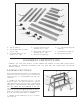
Fig. 4
1. Jointer
2. Belt and Pulley Guard
3. 1/4-20 x 1/2 T russ Head
Screw (2)
4. Guard
5. #8-32 x 1/4 Round Head
Screw
6. Flat Washers (2)
7. #8-32 Hex Nut
8. Dust Chute
9. Cutterhead Guard
UNPACKING AN D CLEANING
The 6 Motorized Jointer is shipped complete in one cont ainer . Carefully unp ack the jointer , st and, and all loose items
from the cont ainer . Figs. 4 and 5 illustrate the items supplied with the jointer .
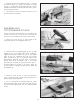
1. W ARNING: For your own safety, DO NOT connect the jointer to a power source until the machine is completely
assembled and you have read and understood the entire owner s manual.
2. IMPORTANT:When removing the jointer from the shipping cont ainer , D O N O T place the jointer on a flat surface.
Support the jointer at both ends with 4 x 4 lumber or similar material, as shown in Fig. 4. This will prevent any dam -
age to the motor assembly, which is located on the base of the jointer .
3. CAUTION: Carefully remove the protective coating from the machined surfaces of the jointer. D O N O T let your
hands or fingers come in cont act with the cutterhead knives as they are extremely sharp. D O N O T use acetone, gaso -
line or lacquer thinner to clean the jointer; use a sof t cloth moistened with kerosene. Af ter cleaning, cover the t able sur -
face with a good quality p aste wax.
10. Fence Mounting Bracket
Assembly
11. Locking Lever
12. Flat Washer
13. 1/4-20 x 3/4 Flat Head
Screws (2)
14. Flat Washers (2)
15. 1-1/4-20 Hex Nut s (2)
16. Fence Support Bracket
17. Cap Screws (2)
18. 5/16-18 x 1-1/4 Hex Head
Screws (3)
19. Flat Washers (6)
20. 5/16 Hex Nuts (3)
21. Push Blocks (2)
22. Fence
23. Flat Washers (2)
24. 1/4-20 x 3/4 Square Head
Screws
25. W renches (4): 2.5, 5, 6mm
and 8/10mm Open-end
1
18
20
19
17
21
22
16
25
23
24
9
8
2
12
11
15
10
14
13
3
4
5
7
6