
Owner`s manual


7
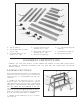
26. Legs for Stand (4)
27. Two Top End Braces for Stand
(10-1/2 long)
28. Two Bottom End Braces for
Stand (15-1/2 long)
Fig. 5
ASSEMBLY INSTRUCTIONS
Fig. 6
29. Top Front and Rear Braces
for S tand (25-1/2 long)
30. Bottom Front and Rear Braces
for S tand (30-1/2 long)
31. Four Feet for S tand Legs
ASSEMBLING STAND
MAKECERTAIN THE MACHINE IS DISCONNECTED
FROM THE POWER SOURCE AND THAT KNIFE
GUARD(A) FIG. 13, IS POSITIONED OVER THE CUT-
TERHEAD.
1. Assemble two top end braces (A) Fig. 6, two top
braces (B) and (C), two lower end braces (D), and two
lower side braces (E) to the four legs (F) as shown using
thirty-two 1/2 long carriage bolt s, flat washers, and hex
nut s. Only tighten hex nut s fingertight at this time .
IMPORTANT:The top lip s of the two upper end braces
(A) must fit on top of two upper side braces (B) and (C).
NOTE: The one top brace (B) with the slotted edge will
be at the rear of the jointer when it is assembled.
2. Assemble the four rubber feet (G) Fig. 6, to the bot -
tom of each leg.
W ARNING: FOR YOUR OWN SAFETY, DO NOT CONNECT THE JOINTER TO THE POWER SOURCE UNTIL
THE JOINTER IS COMPLETELY ASSEMBLED AND YOU HAVE READ AND UNDERSTOOD THE ENTIRE
OWNERS MANUAL.
32. 1/2 Long Carriage Bolt s for
Stand (32)
33. Flat Washers for S tand (32)
34. Hex Nuts for S tand (32)
26
32
33
34
31
30
28
27
29
B
C
A
D
F
G
E
D
A