(Model 37-360, Three Phase) (Model 37-361, Single Phase) PART NO. 1349482 - 02-06-04 Copyright © 2004 Delta Machinery To learn more about DELTA MACHINERY visit our website at: www.deltamachinery.com. For Parts, Service, Warranty or other Assistance, please call 1-800-223-7278 (In Canada call 1-800-463-3582).
SAFETY GUIDELINES - DEFINITIONS This manual contains information that is important for you to know and understand. This information relates to protecting YOUR SAFETY and PREVENTING EQUIPMENT PROBLEMS. To help you recognize this information, we use the symbols below. Please read the manual and pay attention to these sections. Indicates an imminently hazardous situation which, if not avoided, will result in death or serious injury.
GENERAL SAFETY RULES FAILURE TO FOLLOW THESE RULES MAY RESULT IN SERIOUS INJURY. 12. USE THE RIGHT MACHINE. Don’t force a machine or an attachment to do a job for which it was not designed. Damage to the machine and/or injury may result. 13. USE RECOMMENDED ACCESSORIES. The use of accessories and attachments not recommended by Delta may cause damage to the machine or injury to the user. 14. USE THE PROPER EXTENSION CORD. Make sure your extension cord is in good condition.
ADDITIONAL SAFETY RULES FOR JOINTERS FAILURE TO FOLLOW THESE RULES MAY RESULT IN SERIOUS INJURY. 1. 2. 3. 4. 5. 6. 7. 8. 9. 10. 11. 12. 13. 14. DO NOT OPERATE THIS MACHINE until it is completely assembled and installed according to the instructions. A machine incorrectly assembled can cause serious injury. OBTAIN ADVICE from your supervisor, instructor, or another qualified person if you are not thoroughly familiar with the operation of this machine. Knowledge is safety.
POWER CONNECTIONS A separate electrical circuit should be used for your machines. This circuit should not be less than #12 wire and should be protected with a 20 Amp time lag fuse. If an extension cord is used, use only 3-wire extension cords which have 3prong grounding type plugs and matching receptacle which will accept the machine’s plug.
3. Grounded, cord-connected machines intended for use on a supply circuit having a nominal rating between 150 - 250 volts, inclusive: GROUNDED OUTLET BOX CURRENT CARRYING PRONGS If the machine is intended for use on a circuit that has an outlet that looks like the one illustrated in Fig. C, the machine will have a grounding plug that looks like the plug illustrated in Fig. C. Make sure the machine is connected to an outlet having the same configuration as the plug.
DEFINITIONS OF JOINTING AND PLANING OPERATIONS Fig. 2 JOINTING OPERATIONS – Jointing cuts or edge jointing is the simplest and most common operation which can be done on the jointer and these cuts are made to square an edge of a workpiece. The fence is square with the table and the depth of cut is approximately 1/8 inch. The workpiece is positioned on the jointer with the narrow edge of the workpiece on the infeed table and the major flat surface of the workpiece against the fence, as shown in Fig. 2.
UNPACKING AND CLEANING Carefully unpack the machine and all loose items from the shipping container(s). Remove the protective coating from all unpainted surfaces. This coating may be removed with a soft cloth moistened with kerosene (do not use acetone, gasoline or lacquer thinner for this purpose). After cleaning, cover the unpainted surfaces with a good quality household floor paste wax. NOTICE: THE PHOTO ON THE MANUAL COVER ILLUSTRATES THE CURRENT PRODUCTION MODEL.
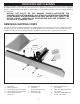
REMOVING MACHINE FROM SHIPPING SKID B C A Fig. 5 Fig. 6 1. Open door (A) Fig. 5, under infeed table and remove mounting hardware that fastens infeed end of machine to skid 2. Remove three screws (B) Fig. 6, and remove cover (C) from dust chute located under outfeed table. Remove mounting hardware located inside cover (C) that fastens outfeed end of machine to skid and replace cover (C). 3. Remove machine from shipping skid and position in permanent location.
ASSEMBLY ASSEMBLING DUST HOOD 1. Assemble the dust hood (A) Fig. 8, to the outfeed end of the jointer base using the seven 5/8″ long button head screws (B) as shown. B B MOVING START-STOP SWITCH TO THE UP POSITION A 1. For shipping purposes, the start-stop switch and switch arm (A) is shipped in the down position, as shown in Fig. 9. Simply remove the two screws (B) Fig. 9, rotate switch and switch arm (A) 180 degrees, as shown in Fig. 10, and replace the two screws (B). B Fig. 8 A B A B Fig.
SINGLE PHASE INSTALLATION IMPORTANT: The jointer cutterhead is a high inertia load which causes the motor to draw a high inrush current during starting. The jointer must be connected to an electrical circuit protected by a properly sized fuse or circuit breaker to handle this high inrush of current. We recommend either a 30 Amp time lag fuse, or a 40 Amp motor start circuit breaker.
THREE PHASE INSTALLATION If the motor on your machine is wired for 200, 230 or 460 Volts, Three Phase, proceed as follows when connecting your machine to an electrical power system. 1. Remove screw (A) Fig. 15, and terminal strip cover (B). B A Fig. 15 2. Remove plastic covering (C) Fig. 16, that snaps into terminal strip. C Fig. 16 3. Bring three phase power line through access hole in bottom of terminal strip box and connect the three power lines to terminals (D) Fig.
OPERATING CONTROLS AND ADJUSTMENTS START-STOP SWITCH A B The start-stop switch is conveniently located on a post, behind the jointer fence, for easy accessibility. To start the machine, simply press the start button (A) Fig. 18, and to stop the machine, press the stop button (B). Fig. 18 FENCE OPERATION 1. The fence (A) Fig. 19, can be moved across the table by loosening lock lever (B) and rotating handwheel (C). After the fence is moved to its desired position, retighten lock lever (B) securely.
ADJUSTING FENCE POSITIVE STOPS C The fence on your jointer is equipped with positive stops at the most used fence positions of 90 degrees and 45 degrees right and left. To check and adjust the positive stops, proceed as follows: B A 1. Position the fence 90 degrees to the table making sure end of stop screw (A) is against stop (B) as shown in Fig. 22. Then tighten lock handle (C). E 2. Using a square (D) Fig. 23, check to see if the fence is at 90 degrees to the table as shown. Fig. 22 3.
B 5. Tilt the fence outward as far as possible and using a combination square (F) Fig. 26, check to see if the fence is tilted outward 45 degrees to the table, as shown. NOTE: 90 degree stop (B) must be rotated up in order to tilt the fence outward. If an adjustment is necessary, loosen lock nut (K) Fig. 27, and adjust screw (L) until head of screw (L) contacts back of fence (M) when the fence is at 45 degrees to the table. F Fig.
OUTFEED TABLE ADJUSTMENTS For most jointing operations the outfeed table must be exactly level with the knives at their highest point of revolution. To move the outfeed table, loosen lock handle ( A ) Fig. 30, and move the table raising and lowering hand lever (B) up or down until the table is level with the knives. A It may be necessary to adjust the positive stops. Loosen the two locknuts (D) and (E) Fig. 31, and the two adjusting screws (F) and (G) when moving the table up or down. B Fig.
4. To adjust belt tension, turn nuts (F) and (G) Fig. 34, to move motor plate (H) up or down until there is approximately 1/2 inch deflection at the center span of the belts, as explained in STEP 3. G F H Fig. 34 ADJUSTING SPRING TENSION OF CUTTERHEAD GUARD A The cutterhead guard (A) Fig. 35, completely covers the cutterhead.
OPERATION CUTTERHEAD ROTATION The rotation of the cutterhead must be in a clockwise direction when viewed from the left side of the machine; that is, the knives must be rotating toward the infeed table from the top. If the cutterhead rotation is incorrect, disconnect the machine from the power source and proceed as follows: Single Phase Machines – Interchange leads T5 and T8 in the motor junction box. Three Phase Machines – Interchange any two of the three incoming power lines.
JOINTING AN EDGE This is the most common operation for the jointer. Set the guide fence square with the table. Depth of cut should be the minimum required to obtain a straight edge. Hold the best face of the piece firmly against the fence throughout the feed as shown in Fig. 37. DO NOT perform jointing operations on material shorter than 10 inches, narrower than 3/4 inch or less than 1/2 inch thick.
TAPER CUTS One of the most useful jointer operations is cutting an edge to a taper. The method can be used on a wide variety of work. Tapered legs of furniture are a common example. Instead of laying the piece on the infeed table, lower the forward end of the work onto the outfeed table. Do this very carefully, as the piece will span the knives and they will take a “bite’” from the work, with a tendency to kickback unless the piece is firmly held. Now push the work forward as in ordinary jointing.
MAINTENANCE REMOVING, REPLACING AND SETTING KNIVES If the knives are removed from the cutterhead for replacement or regrinding, care must be used in removing, replacing and resetting them as follows: 1. DISCONNECT THE MACHINE FROM THE POWER SOURCE. 2. Move the fence to the right until it is clear of the cutterhead. 3. Loosen two screws (A) Fig. 43, and remove cutterhead guard assembly. B E E X T R E M E LY C A R E F U L T H AT YOUR HANDS DO NOT COME IN CONTACT WITH THE KNIVES.
J H 7. IMPORTANT: For ease in rotating the cutterhead during the knife setting operation, pull outward on latch (H) Fig. 46, and open hinged access door (J). This provides access to the cutterhead pulley (K) Fig. 47, and belt (L) allowing you to rotate the cutterhead. Fig. 46 After knives are adjusted, make certain the access door (J) is in the closed and locked position. K 8. Replace the knife locking bars, lifter springs and knives into each slot in the cutterhead.
MAINTENANCE KEEP MACHINE CLEAN LUBRICATION Periodically blow out all air passages with dry compressed air. All plastic parts should be cleaned with a soft damp cloth. NEVER use solvents to clean plastic parts. They could possibly dissolve or otherwise damage the material. Apply household floor paste wax to the machine table and extension table or other work surface weekly. PROTECTING CAST IRON FROM RUST Wear ANSI Z87.1 safety glasses while using compressed air.
PORTER-CABLE • DELTA SERVICE CENTERS (CENTROS DE SERVICIO DE PORTER-CABLE • DELTA) Parts and Repair Service for Porter-Cable • Delta Machinery are Available at These Locations (Obtenga Refaccion de Partes o Servicio para su Herramienta en los Siguientes Centros de Porter-Cable • Delta) ARIZONA Tempe 85282 (Phoenix) 2400 West Southern Avenue Suite 105 Phone: (602) 437-1200 Fax: (602) 437-2200 CALIFORNIA Ontario 91761 (Los Angeles) 3949A East Guasti Road Phone: (909) 390-5555 Fax: (909) 390-5554 Tampa 3360