(Model 37-380) PART NO. 909568 - 07-10-03 Copyright © 2003 Delta Machinery To learn more about DELTA MACHINERY visit our website at: www.deltamachinery.com. For Parts, Service, Warranty or other Assistance, please call 1-800-223-7278 (In Canada call 1-800-463-3582).
SAFETY GUIDELINES - DEFINITIONS This manual contains information that is important for you to know and understand. This information relates to protecting YOUR SAFETY and PREVENTING EQUIPMENT PROBLEMS. To help you recognize this information, we use the symbols to the right. Please read the manual and pay attention to these sections. Indicates an imminently hazardous situation which, if not avoided, will result in death or serious injury.
FAILURE TO FOLLOW THESE RULES MAY RESULT IN SERIOUS PERSONAL INJURY. 1. 2. 3. 4. 5. 6. 7. 8. 9. 10. 11. 12. FOR YOUR OWN SAFETY, READ THE INSTRUCTION MANUAL BEFORE OPERATING THE MACHINE. Learning the machine’s application, limitations, and specific hazards will greatly minimize the possibility of accidents and injury. USE CERTIFIED SAFETY EQUIPMENT. Eye protection equipment should comply with ANSI Z87.1 standards, hearing equipment should comply with ANSI S3.
ADDITIONAL SAFETY RULES FOR JOINTERS FAILURE TO FOLLOW THESE RULES MAY RESULT IN SERIOUS INJURY. DO NOT OPERATE THIS MACHINE until it is completely assembled and installed according to the instructions. A machine incorrectly assembled can cause serious injury. OBTAIN ADVICE from your supervisor, instructor, or another qualified person if you are not thoroughly familiar with the operation of this machine. Knowledge is safety.
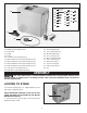
POWER CONNECTIONS A separate electrical circuit should be used for your machines. This circuit should not be less than #12 wire and should be protected with a 20 Amp time lag fuse. If an extension cord is used, use only 3-wire extension cords which have 3prong grounding type plugs and matching receptacle which will accept the machine’s plug.
the plug. No adapter is available or should be used with this machine. If the machine must be re-connected for use on a different type of electric circuit, the reconnection should be made by qualified service personnel; and after re-connection, the machine should comply with all local codes and ordinances. GROUNDED OUTLET BOX CURRENT CARRYING PRONGS I N A L L C A S E S , M A K E C E R TA I N THE RECEPTACLE IN QUESTION IS PROPERLY G R O U N D E D .
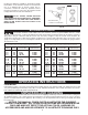
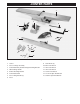
JOINTER PARTS 1 3 4 2 5 6 7 8 10 11 12 13 9 14 15 Fig. 2 1. Jointer 9. Push Blocks (2) 2. Fence Carriage Assembly 10. 6mm Hex Wrench 3. Cutterhead Pulley Guard/Carriage Mounting Bracket 11. 4mm Hex Wrench 4. Table Raising Handle 12. 3mm Hex Wrench 5. Switch Mounting Bracket 13. 2.5mm Hex Wrench 6. Cutterhead Guard 14. 12-14mm Open End Wrench 7. Fence Tilting Handles (2) 15. 8-10mm Open End Wrench 8.
20 27 16 21 22 28 23 29 24 30 25 31 26 32 33 34 35 36 17 18 19 Fig. 3 16. 17. 18. 19. 20. 21. 22. 23. 24. 25. 26. Stand with Pre-Wired Switch Dust Chute V-Belt Pulley 3/8-16x2" Hex Head Screw (3) M8x1.25x55mm Hex Socket Head Screw M8x1.25x25mm Hex Socket Head Screw M8x1.25x20mm Hex Socket Head Screw M8x1.25x16mm Hex Socket Head Screw 5/16-18x1" Hex Head Screw (1) #10-16x1/2" Sheet Metal Screw (4) 27. 28. 29. 30. 31. 32. 33. 34. 35. 36.
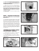
2. Remove the four bolts that attach the motor (A) Fig. 5 to top of the stand. NOTE: SAVE THESE BOLTS AS THEY WILL BE USED TO ATTACH THE MOTOR TO THE MOUNTING BRACKETS. 3. Align the holes in the motor mounting plate (B) Fig. 5A with the four holes in the two motor mounting brackets (C). Attach the motor to the motor mounting brackets with the hardware that was removed in STEP 2. NOTE: MAKE SURE THAT MOTOR SHAFT (D) FIG 5A IS FACING OUT OF THE OPENING IN THE MOTOR CABINET AS SHOWN. A 4.
ASSEMBLING MOTOR PULLEY K Assemble motor pulley (K) Fig. 10, to motor shaft with the hub of the pulley in the outer position as shown. Make certain key (L) is inserted in the keyway of the pulley and motor shaft, then tighten set screw (M) using the 3 mm hex wrench (not shown). L M Fig. 10 ASSEMBLING BELT AND ALIGNING PULLEYS B 1. Place belt (A) Fig. 11, in groove of cutterhead pulley (B) and motor pulley (C). 2. Make certain the motor pulley (C) Figs.
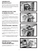
2. Using the supplied 6mm hex wrench (E) Fig. 14, fasten bracket (C) onto jointer base (G). Place a M8.1 lockwasher then an M8 flat washer on an M8x1.25x55mm hex socket head screw. Insert the screw (D) Fig. 14, through the hole in bracket (C), and thread the screw into the jointer base (G), and tighten securely. Repeat this process for the three remaining holes in the bracket and jointer. G D D E C Fig. 14 ASSEMBLING FENCE CARRIAGE ASSEMBLY A 1. Fasten fence carriage assembly (A) Fig.
2. Fig. 18 illustrates fence properly mounted. Fig. 18 3. Thread shorter fence handle (E ) Fig.19, into infeed end of fence (A) and longer fence handle (G) into outfeed end as shown. G E A Fig. 19 C ASSEMBLING CUTTERHEAD GUARD 1. Remove set screw (not shown) from cutterhead guard post (F) with the 2.5mm hex wrench. Insert post (F) through hole in the infeed table. NOTE: A spring is supplied in knob assembly (E) that returns the guard (C) over the cutterhead after a cut has been made.
ASSEMBLING SWITCH AND MOUNTING BRACKET C A E 1. Align the two holes in the switch mounting bracket (A) Fig 22, with the two holes (D) in the back of the infeed table (B). Place an M8.1 lockwasher (E) Fig. 22, then an M8 flat washer (F), on an M8x1.25x16mm hex socket head screw (C). Insert the screw through the hole (D) Fig. 22, in the switch mounting bracket (A) and thread the screw into the tapped hole in the back of the infeed table (B), and tighten securely.
OPERATING CONTROLS AND ADJUSTMENTS STARTING AND STOPPING JOINTER B 1. The on/off switch is located underneath the switch shield (B) Fig. 31. To start the jointer, move switch (A) up to the “ON” position. 2. To turn the jointer “OFF”, push down on switch shield (B) Fig. 32, as shown. A Fig. 31 B Fig. 32 LOCKING SWITCH IN THE “OFF” POSITION IMPORTANT: When the tool is not in use, the switch should be locked in the “OFF” position to prevent unauthorized use. Insert the shank of padlock (C) Fig.
2. Raise or lower the infeed table adjustment lever (C) Fig. 35. B 3. IMPORTANT: When lowering the infeed table, a depth stop (D) Fig. 35, will automatically stop the table at a 1/8" depth-of-cut. To move the table past this point, the depth stop (D) Fig. 36, must be raised, while simultaneously lowering the infeed table. Always make certain table locking handles (A) Fig. 34, and (B) Fig. 35, are tight before operating the jointer.
KNIFE ADJUSTMENTS C In order to do accurate work, the knives must be exactly level with the outfeed table. To check and adjust, proceed as follows: DISCONNECT MACHINE FROM POWER SOURCE. 1. Loosen infeed table lock lever and lower infeed table as described under section “INFEED TABLE ADJUSTMENTS”. Fig. 39 2. Remove cutterhead guard (C) Fig. 39. 3. Place a steel straight edge on the outfeed table, extending over the cutterhead as shown in Fig. 40. 4. Carefully rotate the cutterhead by hand.
ADJUSTING TABLE GIBS “Gibs”’ are provided to take up any play that may develop between the mating dovetailed ways of the base and the infeed and outfeed tables, due to excessive wear. The gib for the infeed table is shown at (A) Fig. 46. Proper gib adjustment is necessary for the functioning of the jointer. The gibs were adjusted at the factory and should not require further adjustment. However, if it ever becomes necessary to adjust the gibs, due to excessive wear, proceed as follows: A Fig. 46 1.
FENCE OPERATION B The fence can be moved across the table and can tilt 45 degrees right or left at any position on the table as follows: NOTE: SWITCH HAS BEEN REMOVED FOR CLARITY OF ILLUSTRATIONS ONLY. 1. To move the fence across the table, loosen lock handle (A) Fig. 50, and turn knob (B) until desired fence location is reached. Then tighten lock handle (A). As the fence is moved across the table, the rear cutterhead guard (C) covers and guards the cutterhead in back of the fence.
4. Rotate flip stop (F) Fig. 54, and tilt the fence outward as far as it will go and tighten locking handle (D). Place a square (K) on the table and against the fence to check if the fence is 45 degrees outward to the table. F M N 5. If an adjustment to the positive stop is necessary, loosen locking handle (D) Fig. 54, and locknut (M). Rotate adjustment screw (N) until you are certain the fence is 45 degrees outward to the table. Tighten locknut (M). D 6. Tilt the fence (G) Fig.
K N I V E S M U S T B E I N S TA L L E D CORRECTLY AS SHOWN IN FIG. 58. 8. The knives are adjusted correctly when the cutting edge of the knife extends out .060” from the cutterhead diameter. 9. Carefully rotate the cutterhead (G) Fig. 59, until the round portion of the cutterhead is on top as shown. Fig. 58 10. Place a .060” feeler gage (H) Fig. 59, on the cutterhead and using a straight edge (J) on the rear table adjust the height of the rear table until it is .
OPERATION The following directions will give the beginner a start on jointer operations. Use scrap pieces of lumber to check settings and to get the feel of the operations before attempting regular work. THE KNIVES ON THE JOINTER WILL NOT WEAR EVENLY BY FEEDING THE WOOD THROUGH THE SAME SPOT ON THE TABLE EVERY TIME. FEED THE WOOD THROUGH THE JOINTER AT DIFFERENT SPOTS ON THE TABLE WHEN POSSIBLE, TO HELP ELIMINATE UNEVEN WEAR OF THE KNIVES. Fig.
SURFACING Surfacing is identical to the jointing operation except for the position of the workpiece. For surfacing, the major flat surface of the workpiece is placed on the infeed table of the jointer with the narrow edge of the workpiece against the fence, as shown in Fig. 64.
SURFACING WARPED PIECES If the wood to be surfaced is dished or warped, take light cuts until the surface is flat. Avoid forcing such material down against the table; excessive pressure will spring it while passing the knives, and it will spring back and remain curved after the cut is completed. SURFACING SHORT OR THIN WORK WHEN SURFACING SHORT OR THIN PIECES, ALWAYS USE PUSH BLOCKS TO MINIMIZE ALL DANGER TO THE HANDS. Fig. 67, illustrates using the Delta Push Blocks properly.
1/2" SQUARES CUT OFF HERE TO PUSH 1/2" WOOD CUT OFF HERE TO PUSH 1/4" WOOD NOTCH TO HELP PREVENT HAND FROM SLIPPING MAKE FROM 1/2" OR 3/4" WOOD OR THICKNESS LESS THAN WIDTH OF MAT’L. TO BE CUT PUSH STICK Narrow pieces of stock that are close to 10 inch minimum length should be handled with a push stick and push block. The Fig. below is a pattern for a push stick.
NOTES 25
NOTES 26
ACCESSORIES A complete line of accessories is available from your Delta Supplier, Porter-Cable • Delta Factory Service Centers, and Delta Authorized Service Stations. Please visit our Web Site www.deltamachinery.com for a catalog or for the name of your nearest supplier. Since accessories other than those offered by Delta have not been tested with this product, use of such accessories could be hazardous. For safest operation, only Delta recommended accessories should be used with this product.
PORTER-CABLE • DELTA SERVICE CENTERS (CENTROS DE SERVICIO DE PORTER-CABLE • DELTA) Parts and Repair Service for Porter-Cable • Delta Machinery are Available at These Locations (Obtenga Refaccion de Partes o Servicio para su Herramienta en los Siguientes Centros de Porter-Cable • Delta) ARIZONA Tempe 85282 (Phoenix) 2400 West Southern Avenue Suite 105 Phone: (602) 437-1200 Fax: (602) 437-2200 CALIFORNIA Ontario 91761 (Los Angeles) 3949A East Guasti Road Phone: (909) 390-5555 Fax: (909) 390-5554 San Leandro