
Instructions / Assembly


4
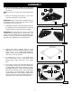
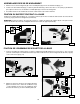
ATTACHING THE LEVELING SCREWS
1. Attach one hex head nut (D) and flat washer (E) to leveling screw (A) Fig. 11.
2. Insert the leveling screw (A) Fig. 11 in the side board (F), through the 7/16" diameter hole drilled earlier. Fasten it
with a second flat washer (B) and hex nut (C).
3. Attach the remaining leveling screw to the other side of the base in the same manner.
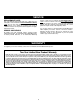
Position the pivot bracket (A) Fig. 12 under the wooden base (B) and fasten with two 2" carriage bolts (C) and hex nuts
(not shown).
NOTE: Insert the carriage bolts (C) Fig. 12 from the inside of the bracket (A) so that the squares underneath the heads
of the carriage bolts fit into the square holes in the pivot bracket (A).
1. Insert the caster assembly (A) Fig. 13 into the pivot bracket (B). Align the holes (C) Fig. 13 with the holes (D) (one
of which is shown) in the caster assembly (A). Fasten with a 4" hex head screw (E) and locknut (F) (Fig. 14).
Fig. 11
Fig. 12
Fig. 13
Fig. 14
ATTACHING THE PIVOT BRACKET TO THE BASE
A
E
D
C
B
F
A
B
A
B
A
C
E
F
D
F
E
ATTACHING THE CASTER ASSEMBLY TO THE BASE
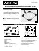
2. Align the two holes (G) Fig. 15 in the pivot bracket (B)
with the two holes - one of which is shown at (H) - in
the foot lever (J). Fasten it with a pin (K), two retain-
ing rings (L), and two flat washers (M).
Fig. 15
C
B
G
L
K
M
J
M
L
H
G