
Installation Sheet


Page 10
209493 Rev. A
www.specselect.com
Installation should be in accordance with local plumbing and electrical codes.
FLUSH ALL PIPES THOROUGHLY BEFORE INSTALLATION.
STEP 1. ROUGH IN
STEP 2. FAUCET INSTALLATION
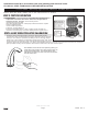
Mount faucet to sink using the provided components in the following
order - grey bottom spacer, washer, lock nut (Fig. 29). NOTE: The
black top spacer must be used at all times between the spout
and countertop/sink, and the grey spacer must be used at all
times between the washer and deck. Ensure open side of bottom
spacer faces up. Washer faces away from sink and must not
touch any conductive surfaces (metal sink, screws, drainage).
If cover plate is being used, it must be between the top spacer and
the deck. Ensure that gasket is sitting inside groove of top spacer.
Use the same procedure for installation of optional 4” or 8” deck
plate package (061159A or 061160A). Mount the faucet to the sink
using nut(s) and washer(s) provided. Do not overtighten the nut or reposition the faucet once
installed, otherwise damage to the gasket may result. Cutting or trimming of the gasket is not
recommended. NOTE: If the gasket is trimmed or not installed, then use clear silicone
sealant between the faucet and lavatory to prevent water from leaking beneath lavatory.
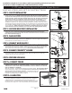
Note: Wires connecting between box(es) and from transformer
must be protected from abrasion and being pulled at connections.
They also may have to be routed through at a later stage of
construction. Depending on installation, the cable bushings included
may be replaced by installer supplied 1/2” conduit. Rough-in box
as per Figure 27.
The transformer is to be installed in an adjacent accessible space.
(Do NOT install the transformer inside the control box.) Cable
from the transformer to the driver board/controller may be roughed
in at this time depending on installation. Use cable which complies
to local electrical codes for a 1 amp load. No.18 is usually sufficient.
If recessed box is supplied, rough in as per Figure 28. The most
vandal resistant installation is when the control box is as close to
the bottom of the sink as feasible. For wall hung sink installation,
sensor conduit rough in should be directly under the basin to
minimize sensor cord exposure. Rough in drainage. Rough in
water supply to 10” control box inlets and to spout connection.
Finish walls.
Valve spacer is for temporary use only for flushing of system. Must
be replaced with solenoid and washers (Figure 28).
STEP 3. CONNECT WATER SUPPLY
Install sink and connect drainage to rough in. See Figure 28. Polymer braided hose (supplied)
must be connected to the spout. Other connection tubes and fittings are supplied by the
installer to connect to the 1/2” nominal sweat at the box outlet. Connect water supply through
to spout. Assure supply lines are completely flushed and free of debris. Install aerator.
Fig. 27
1/2” Sweat
Outlet
Flexible Sensor Cord
Conduit (supplied on
Recessed Mount Box)
Control Box #1
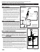
Fig. 28
Tempered Water
(By Others)
Inlet:
1/2” Sweat
060671A
3/4” NPS
Solenoid
Valve &
Washers
061252A
Driver board
to be located
on this bracket
063135A
Stop
590TPxxx1TR Hard Wire Operated Control Box #1 Trim
INSTALLATION AND SET UP INSTRUCTIONS
STEP 4a. CONNECT ELECTRICAL SUPPLY, SOLENOID VALVE
AND SENSOR
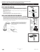
Remove valve spacer and install solenoid valve and washers with body arrow in the direction
of water flow. See Fig. 30. Feed sensor wire from spout into control box and then connect to
the driver board. Connect red solenoid wire from the driver board to “+” marked solenoid
terminal on solenoid valve, black solenoid wire to other solenoid terminal. Attach sensor
module to the faucet shank with the clip. See Fig. 31. Ensure the clip does not contact any
material other than the faucet shank. Connect the sensor cable to the controller board.
IMPORTANT: ENSURE THAT WATER SUPPLY IS ON BEFORE PROCEEDING. WHEN
POWER IS FIRST APPLIED TO THE DRIVER BOARD, THE INSTALLER MUST IMMEDIATELY
STEP BACK AT LEAST 3 FEET FROM THE PROXIMITY SPOUT IN ORDER TO ALLOW THE
UNIT TO PROPERLY CALIBRATE.
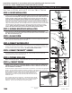
Install CSA and/or UL approved Class 2 transformer or equivalent in a convenient and appro-
priate location. Do NOT install the transformer inside the control box. With the power off,
connect the 24VAC supply from the transformer to the pair of white supply wires coming from
the hardwire converter. Refer to Fig. 32 and Fig. 33 for reference wiring diagrams. Install the
grounding kit assembly (061259A) per the supplied instruction sheet for proper grounding with
Conductive and Non-Conductive sinks.
Turn on power supply for the transformer. 5 quick beeps 3 times will be generated when power
is first applied to the unit. At this stage, step back at least 3 feet from the controller and spout in
order to allow for proper calibration. Do not secure the lid/cover until after calibration.
Grounding cable with copper
clip should be secured directly
to the sink if possible (if sink
is conductive). The clip and
cable should be located and
routed such that accidental
disconnection is unikely.
Product supplied
as shown by solid
lines. All items
shown by dotted
lines supplied by
others.
Typical Installation
(Recessed Mount Box)
Flexible
Sensor
Cord Conduit
Polymer
Braided Hose
257mm (10.13")
Control Box
305mm (12")
Stainless Steel
Cover Plate
102mm (4")
355mm
(14”) max.