
Installation Sheet


Ļ
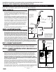
Fig. 5
Page 2
209493 Rev. A
STEP 1. FAUCET INSTALLATION
STEP 3. FLUSH SYSTEM
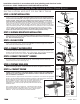
To flush supply line, assemble the bypass adapter as shown (Fig. 3) and run water for one
minute. Shut off water supply. Attach aerator. NOTE: Do not connect supply to the solenoid
inlet until the line is flushed directly out of the spout.
STEP 4. CONNECT WATER SUPPLY
Disassemble the components, reassemble the ones shown here (Fig. 4) supply line and adapter
to the bottom fitting on solenoid, polymer braided spout hose to the top fitting on solenoid. Use
plumber tape where indicated on adapter. Turn on water supply. Must use the polymer braided
hose on both the inlet and outlet of this solenoid. DO NOT SOLDER CONNECTIONS.
STEP 5. CONNECT PROXIMITY
®
SENSOR
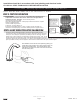
Run the sensor wire out of the battery box through the box openings around the solenoid. Attach
the sensor module to the faucet shank with the clip. Ensure the clip does not contact any
material other than the faucet shank (Fig. 5).
STEP 6. PREPARE SINK AREA
Before connecting the power - clean off counter and remove all objects from the sink.
STEP 7a. CONNECT POWER
IMPORTANT: ENSURE THAT WATER SUPPLY IS ON BEFORE PROCEEDING. WHEN
POWER IS FIRST APPLIED TO THE DRIVER BOARD, THE INSTALLER MUST IMMEDIATELY
STEP BACK AT LEAST 3 FEET FROM THE PROXIMITY SPOUT IN ORDER TO ALLOW THE
UNIT TO PROPERLY CALIBRATE.
Open the control box. Install batteries provided into the battery holder. Do not install 9V battery.
Connect battery clip to battery pack and step back at least 3 feet from the control box and
spout in order to allow for proper calibration. 5 quick beeps 3 times will
be generated when power is first applied to the unit. Do not secure the lid
until after successfully testing for operation (step 8).
Bypass
Adapter
Braided
Polymer
Hose
INSTALLATION AND SET UP INSTRUCTIONS
Installation should be in accordance with local plumbing and electrical codes.
FLUSH ALL PIPES THOROUGHLY BEFORE INSTALLATION.
Fig. 3
www.specselect.com
591TPxxx0 Battery Operated Surface Mount Box #0
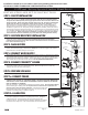
Mount faucet to sink using the provided components in the following order - grey bottom spacer,
washer, lock nut (Fig. 1). NOTE: The black top spacer must be used at all times between
the spout and countertop/sink, and the grey spacer must be used at all times between the
washer and deck. Ensure open side of bottom spacer faces up. The faucet and threaded
shank must not touch any conductive surfaces (metal sink, screws, drainage). If cover
plate is being used, it must be between the top spacer and the deck. Ensure that gasket is
sitting flat on the deck and the faucet is centered on the gasket. Use the same procedure for
installation of optional 4” or 8” deck plate package (061159A or 061160A). Mount the faucet to
the sink using nut(s) and washer(s) provided. Do not overtighten the nut or reposition the faucet
once installed, otherwise damage to the gasket may result. Cutting or trimming of the gasket is
not recommended. NOTE: If the gasket is trimmed or not installed, then use clear silicone
sealant between the faucet and lavatory to prevent water from leaking beneath lavatory.
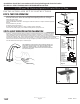
Mount surface mount box to wall under sink using the 4 supplied screws and anchors. Use 1/4”
drill for wall anchors. Be sure to install the box within the dimensions and orientation
provided so the hose and sensor cable will reach connections at faucet and surface mount
box. Refer to illustration (Fig. 2).
STEP 2. SURFACE MOUNT BOX INSTALLATION
STEP 7b. CALIBRATION
After power is applied to the driver board, it generates 5 quick beeps 3
times which prompts the installer to step away from the unit. During the
calibration process, the water will turn ON for several seconds then
proceed to shut off. An additional 5 beeps indicates calibration is complete
and the faucet is ready to use. The cover should be secured at this time.
Fig. 4
Braided
Polymer
Hose
from
spout
Braided
Polymer
Hose
063131A
3/8” Comp
Connect
Nut & Ferrile
Plumber
Tape
Fig. 1
Top Spacer
& Gasket
Washer
Nut
Spout
Bottom Spacer
Sensor
Module
7" (178 mm)
Max.
13" (331 mm)
Max.
Fig. 2
Tie
Wraps
Braided
Polymer
Hose
Threaded
Shank