
Installation Sheet


Ļ
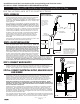
Fig. 17
Page 7
www.specselect.com
STEP 5a. CONNECT ELECTRICAL SUPPLY,
SOLENOID VALVE & SENSOR
Cover
Fig. 16
Valve
Spacer
(Replace
with
SOLENOID
Valve and
washers
after system
is flushed)
Solenoid Valve
(INSTALL:
replacing
SPACER after
system is
flushed.)
SOLENOID
may be
ROTATED to
ALLOW for installation
of COVER ASSEMBLY.
209493 Rev. A
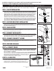
Remove valve spacer and install solenoid valve and washers
with body arrow in the direction of water flow. See Fig. 16.
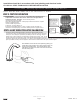
Feed sensor wire from spout into control box and then connect
to the driver board. Connect red solenoid wire from the driver
board to “+” marked solenoid terminal on solenoid valve, black
solenoid wire to other solenoid terminal. Attach sensor module
to the faucet shank with the clip. See Fig. 17. Ensure the clip
does not contact any material other than the faucet shank.
Connect the sensor cable to the controller board.
IMPORTANT: ENSURE THAT WATER SUPPLY IS ON
BEFORE PROCEEDING. WHEN POWER IS FIRST APPLIED
TO THE DRIVER BOARD, THE INSTALLER MUST
IMMEDIATELY STEP BACK AT LEAST 3 FEET FROM THE
PROXIMITY SPOUT IN ORDER TO ALLOW THE UNIT TO
PROPERLY CALIBRATE.
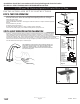
Open the control box. Install batteries provided into the battery
holder. Do not install 9V battery. Connect battery clip to
battery pack and step back at least 3 feet from the control
box and spout in order to allow for proper calibration. 5
quick beeps 3 times will be generated when power is first
applied to the unit. Do not secure the lid until after success-
fully testing for operation (step 7).
STEP 5b. CALIBRATION
After power is applied to the driver board, it generates 5 quick
beeps 3 times which prompts the installer to step away from
the unit. During the calibration process, the water will turn ON
for several seconds then proceed to shut off. An additional 5
beeps indicates calibration is complete and the faucet is ready
to use. The cover should be secured at this time.
STEP 6. TEST FOR OPERATION
Test for operation. If OK, then close lid - Use caution not to damage wires or
components on electronic driver board. Route wires through notches/openings
in the box. See Fig 18. Secure lid using screws.
If faucet leaks from spout outlet:
SHUT OFF WATER SUPPLIES. Check proper solenoid connection. Replace solenoid
if problem persists.
If faucet exhibits very low flow:
A) Remove and clean Aerator, or
B) SHUT OFF WATER SUPPLY. Clean or replace Screen Assembly. If unit does not
work properly, see Trouble Shooting Guide on pages 16 & 17.
STEP 7. BASIC OPERATION AFTER CALIBRATION
Proximity
®
sensing technology works by creating an electrical field around a conductor
(the spout) and monitoring the change in capacitance that the conductor undergoes.
The change in capacitance (the ability to store an electrical charge) is brought on by a
2nd conductor (a human body) entering the Proximity
®
field. As the human hand enters
and leaves the vicinity of the electrical field around the spout, the solenoid is opened and
closed accordingly. It is critical in the installation process that all electrical and mechanical connections be as tight and rigid as possible,
ensuring a smooth signal is carried from the driver board to the spout, and back again.
Fig. 15
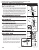
Towards
“H” side to
increase
temperature
Towards
“C” side
to reduce
temperature
Fig. 18
DO NOT
INSTALL
9V
BATTERY
591TPxxx8TR Battery Operated Control Box #8 Trim
Installation should be in accordance with local plumbing and electrical codes.
FLUSH ALL PIPES THOROUGHLY BEFORE INSTALLATION.
INSTALLATION AND SET UP INSTRUCTIONS
Fig. 14
Top Spacer
& Gasket
Washer
Nut
Spout
Bottom Spacer
Sensor
Module
After calibration, test the function of the product by placing your
hands within close proximity of the spout (ensuring hands are
moving as if washing hands). The solenoid will stay open
while hands are moving, then close once hands are removed
from the sensing zone.
Water