
Installation Guide

Page 3
210317 Rev. A
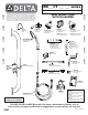
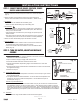
Typical Installations
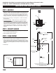
Fig. 3
2,007mm
(79”)
Recommended
Mounting Height
860T167 860T168
860T163
860T166
Top of Box
1,320mm
(52”)
Recommended
Mounting Height
to top of Box
Finished Floor
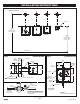
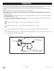
Fig. 4
6mm
(1/4”) min.
35mm
(1-3/8”) max.
55mm
(2-5/32”)
Finished Wall
V.R. Screws (4)
114mm
(4-1/2”)
102mm
(4”)
060986A
Stainless Steel Cover Plate
Stainless Steel Push Button
Plaster Guard
Standard Electrical Box
102 x 102mm (4” x 4”)
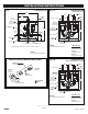
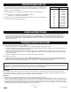
Fig. 5
203mm
(8”)
102mm
(4”)
Outlet
3/8” M.I.P.
Control Box
060983A
860T Driver
Board
206mm
(8-1/8”)
060671A
Slow Closing
Solenoid Valve
063135A
Screwdriver
Stop
Inlet
1/2” Copper
Tempered Water
(By Others)
Control Box #6
060671A
Slow closing
solenoid valve
063135A
Screwdriver
Stop
Inlet
1/2” M.I.P/
1/2” copper sweat
Outlet
3/8” F.I.P.
Control Box #3
060985A
10” x 10” Stainless Steel Cover
▼ ▼
▲
▼
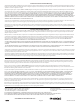
INSTALLATION INSTRUCTIONS
▲
114mm
(4-1/2”)
www .specselect.com
The stop and solenoid will need to
be mounted in a separate accessible
location. Cannot be installed in the
4” rough-in box.