
Installation Guide
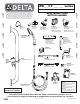

Page 5
210317 Rev. A
STEP 5 - TURN ON WATER, ADJUST AND REPLACE
COVERS
5.1 Pressure Balanced Valve
● Install cartridge. (Note: for cartridge installation instructions and back to back installations, refer to pages 3 to 6 of the included
MultiChoice™ Valve Trim instructions.)
● Open screwdriver stop(s) to supply water to the shower.
● Press the stainless steel button to start the flow of water.
● Adjust to desired water temperature (page 6 of the MultiChoice™ Valve Trim
instructions).
● Ensure that the stickers contained within the MultiChoice™ Valve Trim instructions
are applied accordingly.
● Advance to step 5.3.
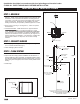
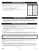
5.2 Thermostatic Mixing Valve
● To adjust the mixed outlet temperature of the valve, remove the cap to gain access
to the adjusting spindle.
● The spindle should be rotated towards the “C” side to reduce the temperature and
towards the “H” side to increase the temperature - until the desired set point is
reached (refer to Fig. 11).
Periodic Inspection/Maintenance
● We recommend that this valve is checked at least once per year to ensure its continued function.
For installations with poor or unknown water quality, or other adverse supply conditions, it may be
necessary to check the valve at more frequent intervals. The temperature should be checked at the
same outlet as was used for commissioning in the first instance. If the temperature is more than 3°F
from the commissioning in temperature, refer to the included Cash Acme Maintenance & Installation
Guide.
5.3 All Models
● Replace covers using vandal resistant screws and drivers supplied.
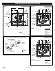
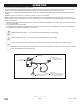
Fig. 10
To Driver Board
Yellow Button Wires
060679A
Stainless Steel Button Assembly
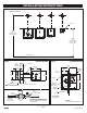
STEP 4 - CONNECT DRIVER BOARD, SOLENOID, POWER
SUPPLY AND OVERRIDE BUTTON
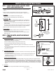
● Remove valve spacer and replace with solenoid valve (Fig. 9). Note flow
direction marked on the valve body and install in the correct orientation
(Fig. 8).
● Attach the black and red solenoid wires on the driver board to the
solenoid. Red wire attaches to the terminal marked “+”, Black wire to “-”.
● For Battery -
▪ Install 4 fresh “AA” batteries into the battery pack.
▪ Attach the driver board battery clip to the battery pack.
● For Hardwire -
▪ Install CSA and/or UL approved class 2 transformer or equivalent in a
convenient location in an adjacent accessible space, either above the
ceiling or in an access chase.
▪ Have transformer connected to the power supply as required by local
electrical codes.
▪ Run cable from the secondary side of the transformer to the control box,
if not already done, and connect to the hardwire converter (060683A).
● Attach the driver board battery clip to the hardwire converter.
● Override Button -
▪ Use the supplied button extension wire and connect the male ends to
the override button wires (yellow) of the driver board.
▪ Connect the female ends of the extension cord to the stainless steel
button (Fig. 10).
Slow closing
solenoid valve
AND
Screwdriver
Stop
Fig. 8
Inlet
1/2” M.I.P/
1/2” copper sweat
Outlet
3/8” F.I.P.
060984A
Button Extension Wire
Fig. 11
Towards
“H” side to
increase
temperature
Towards
“C” side
to reduce
temperature
INSTALLATION INSTRUCTIONS
www .specselect.com
Spacer
(replace with
SOLENOID
valve after
system is
flushed)
Cover
Assembly
NOTE:
flow direction
ARROW
on bottom
Slow closing
solenoid valve
(INSTALL: replacing
spacer after system
is flushed)
Water flow
Fig. 9