(Model 43-505) PART NO. 902118 (0112) Copyright © 2001 Delta Machinery To learn more about DELTA MACHINERY visit our website at: www.deltamachinery.com. For Parts, Service, Warranty or other Assistance, please call ESPAÑOL: PÁGINA 19 1-800-223-7278 (In Canada call 1-800-463-3582).
GENERAL SAFETY RULES Woodworking can be dangerous if safe and proper operating procedures are not followed. As with all machinery, there are certain hazards involved with the operation of the product. Using the machine with respect and caution will considerably lessen the possibility of personal injury. However, if normal safety precautions are overlooked or ignored, personal injury to the operator may result.
ADDITIONAL SAFETY RULES FOR FOR THE ROUTER/SHAPER WARNING: FAILURE TO FOLLOW THESE RULES MAY RESULT IN SERIOUS PERSONAL INJURY 1. DO NOT OPERATE THIS MACHINE UNTIL it is assembled and installed according to the instructions. 2. OBTAIN ADVICE from your supervisor, instructor, or another qualified person if you are not familiar with the operation of this machine. 3. FOLLOW ALL WIRING CODES and recommended electrical connections. 4.
POWER CONNECTIONS A separate electrical circuit should be used for your machines. This circuit should not be less than #12 wire and should be protected with a 20 Amp time lag fuse. If an extension cord is used, use only 3-wire extension cords which have 3prong grounding type plugs and matching receptacle which will accept the machine’s plug.
EXTENSION CORDS Use proper extension cords. Make sure your extension cord is in good condition and is a 3-wire extension cord which has a 3-prong grounding type plug and matching receptacle which will accept the machine’s plug. When using an extension cord, be sure to use one heavy enough to carry the current of the machine. An undersized cord will cause a drop in line voltage, resulting in loss of power and overheating. Fig. D, shows the correct gauge to use depending on the cord length.
ASSEMBLY WARNING: FOR YOUR OWN SAFETY, DO NOT CONNECT THE MACHINE TO THE POWER SOURCE UNTIL THE MACHINE IS COMPLETELY ASSEMBLED AND YOU READ AND UNDERSTAND THE ENTIRE INSTRUCTION MANUAL. ASSEMBLING ACCESSORY STAND If you purchased the accessory stand for use with your Router/Shaper, the stand must be assembled as follows: 1. Remove the rubber feet from the bottom of the Router/Shaper. 2. Assemble the stand as shown in Fig. 2.
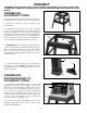
ASSEMBLING OVERHEAD CUTTER GUARD BRACKET Assemble the overhead cutter guard holding bracket (A) Fig. 6, to the rear of the Router/Shaper and fasten with the two M6x10mm sheet metal screws (B). B B A ASSEMBLING AND INSTALLING FENCE ASSEMBLY AND DUST CHUTE Fig. 6 Two fence halves are supplied as standard equipment with the Router/Shaper. To assemble and install the fence assembly, proceed as follows: R E G 1. NOTE: The fence body with the see-thru cutter guard (R) Fig.
6. Place dust hood (P) Figs. 9 and 10, over dust chute (H) and fasten dust hood to back of fence body (A) using two M5x10mm sheet metal screws (S), as shown in Fig. 10. NOTE: Dust hood (P) should always be used. Dust chute (H) is used only with a dust collection system. A S ASSEMBLING TABLE INSERT The table insert (A) is assembled in the table, as shown in Fig. 11. P H FASTENING ROUTER/SHAPER TO SUPPORTING SURFACE Fig.
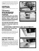
OVERLOAD PROTECTION The Router/Shaper is equipped with overload protection. If the motor shuts off, or fails to start due to overloading (cutting stock too fast; using dull bits and cutters; using the machine beyond its capacity or at low voltage, etc.), TURN THE SWITCH (A) FIG. 16, TO THE “OFF” POSITION. Let the motor cool three to five minutes and push the overload reset button (C) which will reset the overload device. The machine can then be turned on again in the usual manner.
SEE-THRU CUTTER GUARD A The see-through cutter guard (A) Fig. 20, should always be used when using the fence to guide the work. The guard (A) raises as the workpiece is pushed along the fence and lowers at the completion of the cut. Fig. 20 The guard (A) can be moved up and out of the way as shown in Fig. 21, when changing bits and cutters. A WRENCH STORAGE The Router/Shaper is supplied with two wrenches (A) Fig. 22.
5. Loosen adjustment bolt (D) Fig. 24, and corresponding bolt at the rear of the machine (not shown.). A 6. Carefully move the spindle height lock knob (E) Fig. 24, up or down until the metal rod (A) is 90 degrees to the table surface. Then tighten adjustment bolts (D) which were loosened in STEP 5. E D Fig.
INSTALLING ROUTER BITS 1. DISCONNECT MACHINE FROM POWER SOURCE. 2. Raise spindle to the maximum height and tighten lock knob. 3. This machine is supplied with a 1/2 inch collet (A) Fig. 27, that accepts 1/2 inch shank router bits. A 1/4 inch adapter sleeve (B) Fig. 28, is also furnished that allows you to use 1/4 inch shank router bits. 4. Insert 1/2 inch collet (A) Fig. 27, into spindle assembly (C) and hand tighten nut (D).
INSTALLING OVERHEAD CUTTER GUARD D An overhead cutter guard, shown in Fig. 31, is supplied as standard equipment with your Router/Shaper and should always be used for operations that require the fence to be removed. To install the overhead cutter guard, proceed as follows: C 1. DISCONNECT MACHINE FROM POWER SOURCE. E 2. Remove the fence assembly from the table. 3. Insert rod (A) Fig. 31, of overhead cutter guard through hole in rear of table, as shown, and into bracket (C).
OPERATION The following is an example of the setting-up and operational procedures when using the fence, collars and starting pin. Please review this information carefully before turning on the power to avoid damage to the machine or personal injury. WARNING: The use of accessories and attachments not recommended by Delta may result in risk of injuries.
POSITION OF COLLARS 1. The collars may be used in any of the following positions: above, below or between two cutters. CUTTER COLLAR 2. When the collar is used below the cutter, as shown in Fig. 43, the progress of the cut can be observed at all times. However, any accidental lifting of the work will gouge the wood and ruin the workpiece. WORK TABLE Fig. 43 3. When the collar is used above the cutter as shown in Fig.
ACCESSORIES A complete line of accessories is available from your Delta Supplier, Porter-Cable • Delta Factory Service Centers, and Delta Authorized Service Stations. Please visit our Web Site www.deltamachinery.com for a catalog or for the name of your nearest supplier. WARNING: Since accessories other than those offered by Delta have not been tested with this product, use of such accessories could be hazardous. For safest operation, only Delta recommended accessories should be used with this product.
NOTES 17
NOTES 18