
Router/Shaper Instruction Manual


13
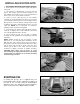
INSTALLING OVERHEAD
CUTTER GUARD
An overhead cutter guard, shown in Fig. 31, is supplied
as standard equipment with your Router/Shaper and
should always be used for operations that require the
fence to be removed. To install the overhead cutter
guard, proceed as follows:
1. DISCONNECT MACHINE FROM POWER SOURCE.
2. Remove the fence assembly from the table.
3. Insert rod (A) Fig. 31, of overhead cutter guard
through hole in rear of table, as shown, and into bracket
(C). NOTE: It may be necessary to loosen bracket (C) in
order to insert rod (A). Adjust the height of the overhead
guard (D) until the rim of the guard (D) lays flat on the
workpiece and tighten two screws, both of which are
shown at (E) Fig. 31. The guard raises as the workpiece
moves against the cutter, and lowers at the completion
of the cut.
Fig. 31
Fig. 32
Fig. 33
Fig. 34
Fig. 35
INSTALLING ACCESSORY
SHAPER SPINDLE
An optional 1/2” shaper cutter spindle that accommo-
dates 1/2” bore shaper cutters is available for use with
your Router/Shaper and can be installed as follows:
1. DISCONNECT MACHINE FROM POWER SOURCE.
2. Raise spindle as far as it will go and lock spindle
height lock knob.
3. Assemble collet (A) Fig. 32.
4. Insert accessory shaper spindle (B) Fig. 33, into
collet (A). Tighten shaper spindle (B) Fig. 34, in collet (A)
using wrenches supplied (C).
5. Fig. 35, illustrates the shaper spindle (B) and shaper
cutter (D) installed in the collet (A). After installing shaper
cutter, fences (E) Fig. 35, should be moved as close as
possible to the cutter (D) without touching. IMPORTANT:
Always use table insert whenever possible.
D
A
C
E
E
A
A
B
B
A
C
C
E
E
A
B
D