
Router/Shaper Instruction Manual


7
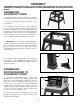
ASSEMBLING OVERHEAD
CUTTER GUARD BRACKET
Assemble the overhead cutter guard holding bracket (A)
Fig. 6, to the rear of the Router/Shaper and fasten with
the two M6x10mm sheet metal screws (B).
Fig. 6
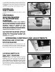
ASSEMBLING AND
INSTALLING FENCE
ASSEMBLY AND DUST
CHUTE
Two fence halves are supplied as standard equipment
with the Router/Shaper. To assemble and install the
fence assembly, proceed as follows:
1. NOTE: The fence body with the see-thru cutter
guard (R) Fig. 7, assembled to it, is to be assembled to
the right hand side of the table. Place keyed bottom
portion of the left hand fence body (A) Fig. 7, in table slot
(B). Insert a 5/16-18x1-1/4" carriage head bolt (C) up
through bottom of table slot (B), place a 5/16" flat
washer on bolt and secure with lock handle.
2. Place back of wooden fence (E) Fig. 7, against front
of fence body (A), as shown. Line up hole in wooden
fence (E) with slot (F) in fence body (A) and fasten
wooden fence (E) to fence body by inserting a 3/8-16x1-
1/2" screw through hole in wooden fence and hole in
fence body thread a 3/8-16 hex nut (G) onto the 3/8-
16x1-1/2" screw.
3. Assemble the right hand fence assembly (T) Fig. 7,
to the table in the same manner.
Fig. 7
4. If you will be connecting your Router/Shaper to a
dust collection system, assemble the dust chute (H) Fig.
8, to the rear of the table by fastening bottom lip (M) of
dust chute to sheet metal plate (N) using two M4x8mm
sheet metal screws (J). IMPORTANT: Make certain the
slot (K) in dust chute fits snugly around table lip (L). Also
make certain lip (M) of dust chute, is underneath sheet
metal plate (N). NOTE: If a dust collection system is not
going to be used, do not attach the dust chute.
Fig. 8
Fig. 9
5. Fig. 9, illustrates the dust chute (H) assembled to the
table.
A
B
B
R
T
E
F
A
C
B
D
K
M
J
N
H
H
P
A
G