
Use and Care Manual


7
ASSEMBLY
PEDAL ASSEMBLY
ASSEMBLE PEDAL ASSEMBLY TO
MAIN FRAME ASSEMBLY
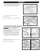
Attach both Cross Tube Supports (H & I) with M6 x 40 mm Hex
Bolts (O) using Wrench (J). Repeat this step on the other side
of this assembly. (Figure 5)
This creates the Support Leg Rod Assembly (1). See Figure 4
for assembled image.
Remove Locknut (c) and 1st Flat Washer (b) from wheel axels
on Pedal Assembly (A). Leave 2nd washer on axel. Install
wheel onto axel with Triad Logo facing out. (Figure 6)
Add 1st Flat Washer (b) and tighten Locknut (C) onto Axel with
Wrench (J), ensuring that wheel can still roll freely (Figure 7).
Repeat these steps on axel on far side of this assembly.
Attach Pedal Assembly (A) to Stand Main Frame Assembly
(B) as shown in Figure 8 using M8 x 87mm Carriage Bolt (K),
Plastic Spacer (M) and M8 Locknut (N).
Ensure Carriage Bolt (K) ts properly into square hole in tube.
Plastic Spacer (M) will be placed between the tubes as shown
in Figure 8a. Tighten Locknut (N) with Wrench (J) to secure
assembly so that spacer is a snug t between the two tubes.
Repeat on other side of this assembly.
Note: Do not over tighten Locknut (N). Over tightening will
aect stand folding performance.
Note: Pedal lock mounted to pedal assembly should be on the
same side as lock pin on main frame assembly.
Figure 5
Figure 6
Figure 7
Figure 8
Figure 8a
N
M
K
B
K
A
M
N
b
c
A
a
b
c
H
I
O
Lock Pin
Pedal Lock