
Use and Care Manual


9
ASSEMBLY
TILE SAW INSTALLATION TO STAND
Install M8 x 45mm Carriage Bolt (Q) through outer side of
tube. Ensure that the Carriage Bolt (Q) ts properly into square
hole on tube (Figure 13). Tighten M8 Locknut (U) with Wrench
(J). Repeat these steps on other side of this assembly.
Your assembled stand is now ready for the Tile Saw
installation. (Figure 14)
Note: Left Hand Handle is item F1. Right Hand Handle is item
F2.
Figure 13
Figure 14
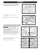
Note: This is a TWO MAN LIFT operation!
Place Tile Saw on stand as shown in Figure
15. (Image is of the 7 in. Tile Saw on this stand)
The 10 in. Tile Saw will t on the outer most rail of the Main
Frame Assembly. Figure 15 shows 7 inch tile saw and Figure 16
shows 10 in tile saw installation.
Note: Motor Head Support Arm of Tile Saw should be on the
end that has both rails (7 in. & 10 in.). Secure Tile Saw to
stand with Wrench (J) using the four M8 x 40mm wing screw
assembly (P). Wing screw/washer assembly is inserted up
through the rail and screwed into the Foot Pad/Tile Saw Frame
on the Tile Saw as shown in Figure 15 and Figure 16.
Once all four wing screws have been secured, your tile saw is
now ready for transport. (Figure 17)
Note: Tile saw is not included with stand.
Figure 15 Figure 16
Figure 17
Stand Assembly
with 7 in. Tile
Saw
Stand Assembly
with 10 in. Tile
Saw
Step Pedal
Lock
Step Pedal
Lock
7 in.
Support Rail
10 in.
Support Rail
P
7 in.
Support
Rail
10 in.
Support
Rail
Q
S
F1
F2
P