http://www.delta.com.
B Series Temperature Controller User Manual 1 Precaution DANGER! Caution! Electric Shock! 1. Do not touch the AC terminals while the power is supplied to the controller to prevent an electric shock. 2. Make sure power is disconnected while checking the unit inside. 3. The symbol indicates that this Delta B Series Temperature Controller is protected throughout by DOUBLE INSULATION or REINFORCED INSULATION (equivalent to Class II of IEC 536). WARNING! This controller is an open-type temperature controller.
4 Input Voltage Operation Voltage Range Power Consumption Memory Protection Display Method Sensor Type Control Mode Control Output Display Accuracy Sampling Rate RS-485 Communication Vibration Resistance Shock Resistance Ambient Temperature Storage Temperature Altitude Relative Humidity Specifications 100 to 240VAC 50/60Hz 85% to 110% of rated voltage 5VA max.
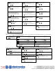
Operation 6 There are three modes of operation: operation, regulation and initial setting. When power is applied, controller gets into the operation mode. Press the key to switch to regulation mode. If the mode. Pressing the key is pressed for more than 3 seconds, controller will switch to the initial setting key while in the regulation mode or initial setting mode, forces the controller to return to the operation mode. PV/SV: Sets the temperature set point and displays the temperature process value.
Display and adjust output value of 1st output group (Display in PID control mode and manual RUN mode) Time setting for valve from full close to full open. (Display when valve control is ON) Press ASCII, RTU communication format selection Press Press Display and adjust output value of 2nd output group (Display in dual loop PID control mode and manual RUN mode) Press Valve Dead Band setting. (Display when valve control is ON) Press Upper-limit regulation of valve output with feedback to controller.
Dual Loop Output Control (Heating / Cooling Control) 7 Dead band Temperature control can be achieved either by heating or cooling. In DTB series, heating and cooling can be operated simultaneously (Dual Loop output control) to perform temperature Cooling hysteresis control. When Dual Loop output control are used, two control outputs must be connected to the Heating hysteresis ON heating and cooling devices.
8 Alarm Outputs There are up to three groups of alarm outputs and each group allows thirteen alarm types in the initial setting mode. The alarm output is activated whenever the process temperature value (PV) is getting higher or lower than the set point of alarm limit.
9 Current Transformer (CT) Function The Current Transformer (CT) function is used with the alarm output. When using a current transformer (CT) with the controller, change the corresponding alarm output mode to mode 13 (alarm output set value is 13), then turn to operation mode and set the current lower-limit and current upper-limit. You can set current alarm range between 0.5A ~ 30A, display resolution is 0.1A and measure accuracy is +/- 0.5A.
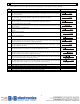
13 RS-485 Communication 1. 2. 3. 4. Supporting transmission speed: 2400, 4800, 9600, 19200, 38400bps Non-supported formats: 7, N, 1 or 8, O, 2 or 8, E, 2 Communication protocol: Modbus (ASCII or RTU) Function code: 03H to read the contents of register (Max. 8 words). 06H to write 1 (one) word into register. 02H to read the bits data (Max. 16 bits). 05H to write 1 (one) bit into register. 5. Address and Content of Data Register: Address Content Explanation Measuring unit is 0.1, updated one time in 0.
30H 1040H~ 1047H 1050H~ 1057H 1060H~ 1067H Start pattern number 0~7 Actual step number setting inside the 0 ~ 7 = N, indicate that this pattern is executed from step 0 to step N correspond pattern Cycle number for repeating the 0 ~ 99 indicate that this pattern has been executed for 1 ~ 100 times execution of the correspond pattern Link pattern number setting of the 0 ~ 8, 8 indicates the program end.
Panel Cutout and Terminals Identification Terminals Identification Panel Cutout (dimensions are in millimeter and inch) 65.0 min. (2.56) DTB4824 40.0 min. (1.58) +0.6 22.0 -0 (0.87) +0.02 -0 OUT 2/ ALM + V L 44.8 (1.76) DTB4848 +0.6 -0 +0.02 -0 8 2 7 1 mm (in) N RS-485 - 60.0 min. (2.36) 10 11 5 4 RTD ! OUT1 14VDC or 4~20mA or 0~10V NO COM + +0.6 45.0 -0 +0.02 (1.
15 External Dimensions Dimensions are in millimeter (inch) DTB4824 DTB4848 22.0 mm (0.87 in) 45.0 mm +0.6 0 (1.77 in)+0.02 0 44.75 mm (1.76 in) +0.6 48.0 mm (1.89 in) 3.4 mm (0.13 in) 48.0 mm (1.89 in) 21.85 mm (0.86 in) 24.0 mm (0.94 in) 44.8 mm (1.76 in) 48.0 mm (1.89 in) 99.8 mm (3.93 in) 80.0 mm (3.15 in) 9.5 mm (0.37 in) DTB9696 +0.6 91.5 mm +0.6 0 (3.60 in) +0.02 0 44.0 mm (1.73 in) 91.0 mm 0 (3.58 in)+0.02 0 DTB4896 44.75 mm (1.76 in) 45.0 mm 0 (1.77 in) +0.02 0 +0.6 48.
Mounting 16 Mounting Method Mounting Bracket Installation Step 1 : Insert the controller through the panel cutout. Step 2 : Insert the mounting bracket into the mounting groove at the top and bottom of the controller Step 3 : Push the mounting bracket forward until the bracket stops at panel wall. Step 4 : Insert and tighten screws on bracket to secure the controller in place. (The screw torque should be 0.8kgf-cm to 1.