
User's Manual


5
VFD-F Series
DELTA ELECTRONICS, INC. ALL RIGHTS RESERVED
5-47
If you set BB action by this parameter and you also need to disable BB action by this
parameter.
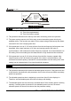
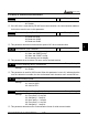
There is a built-in RS-485 serial interface, marked (RJ-11 jack) on the control terminal block.
The pins are defined below:
6
1
1: EV
2: GND
3: SG-
4: SG+
5: NC
6: for communication
Each AC drive has a pre-assigned communication address specified by 9-00. The
computer then controls each AC drive according to its communication address.
AC drive can be setup to communicate on Modbus networks using one of the following
modes: ASCII (American Standard Code for Information interchange) or RTU (Remote
Terminal Unit). Users can select the desired mode along with the serial port communication
protocol in 09-04 and 09-05.
Code Description:
ASCII mode:
Each 8-bit data is the combination of two ASCII characters. For example, a 1-byte
data: 64 Hex, shown as ‘64’ in ASCII, consists of ‘6’ (36Hex) and ‘4’ (34Hex).
Character ‘0’ ‘1’ ‘2’ ‘3’ ‘4’ ‘5’ ‘6’ ‘7’
ASCII Code 30H 31H 32H 33H 34H 35H 36H 37H
Character ‘8’ ‘9’ ‘A’ ‘B’ ‘C’ ‘D’ ‘E’ ‘F’
ASCII Code 38H 39H 41H 42H 43H 44H 45H 46H
RTU mode:
Each 8-bit is the combination of two 4-bit hexadecimal characters. For example, 64 Hex.
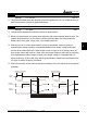
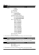
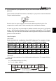
2. Data format
2.1 10-bit character frame ( for 7-bit ) :
(7 , N , 2 : 9-04=0, 9-05=0)
0123456
Start
bit
Stop
bit
Stop
bit
7-bit character
10-bit character frame