
User's Manual

Air Pressure
Air Flow
(mm H
2
O)
(IN H
2
O)
(M
3
/MIN)
(CFM)
UNIT :
(INCH)
mm
UNIT :
(INCH)
mm
INLET SIDE
OUTLET SIDE
HH
H
M
L
0 0.6 1.2 1.8 2.4
0
0.06
0.12
0.18
0.24
0.30
0.36
4.5
0
1.5
3.0
6.0
7.5
9.0
.075.045 .060.030.0150
AFB02505/12XA-A
LABEL
20.0±0.3
25.0±0.5
(0.984±0.020)
(0.787±0.012)
(0.787±0.012)
(0.984±0.020)
25.0±0.5
20.0±0.3
10.0±0.5
(0.394±0.020)
10.0
150.0±10.0
(0.394)
(5.906±0.394)
4-Ø2.8±0.3
(4-Ø0.110±0.012)
20.0
(0.787)
(0.787)
20.0
Ø24.0
(Ø0.945)
20.0
(0.787)
(0.787)
20.0
(Ø0.945)
Ø24.0
4-Ø2.8
(4-Ø0.110) (4-Ø0.110)
4-Ø2.8
http://www.deltaww.com
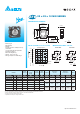
AFB
■
DIMENSIONS DRAWING
■
P & Q CURVE
(AT RATED VOLTAGE)
■
MOUNTING PANEL CUTOUT
25 x 25 x 10 MM SERIES
*
Bearing Type
Ball Bearings
*
Material
Impeller & Frame : Plastic(UL 94V-0)
*
Lead Wires :
UL 1061 AWG #26 OR Equivalent
Red Wire Positive(+)
Black Wire Negative(-)
*
Weight : 10.5g (0.37 OZ)
*
Rib Type Only & One Side Flange
MODEL
Rated
Voltage
Operating
Voltage
Range
Input
Current
Input
Power
Speed
Maximum
Air Flow
Maximum
Air Pressure
Noise
PART NO.
REV.
FUNCTION VDC VDC Amp Watt R.P.M. m
3
/min CFM mmH
2
O IN H
2
O dB-A
AFB02505LA -A -R00 / -F00 5 4.0 to 5.5 0.04 0.20 5000 0.024 0.85 1.15 0.045 18.0
AFB02505MA -A -R00 / -F00 5 4.0 to 5.5 0.06 0.30
7000 0.034 1.20 2.18 0.085 20.0
AFB02512MA -A -R00 / -F00 12 9.5 to 13.2 0.04 0.48
AFB02505HA -A -R00 / -F00 5 4.0 to 5.5 0.12 0.60
10000 0.052 1.84 4.48 0.176 23.5
AFB02512HA -A -R00 / -F00 12 7.0 to 13.2 0.06 0.72
AFB02505HHA -A -R00 / -F00 5 4.0 to 5.5 0.16 0.80
13000 0.068 2.40 7.65 0.300 28.0
AFB02512HHA -A -R00 / -F00 12 7.0 to 13.2 0.08 0.96
* Function type is optional.
* The max. air ow and the speed are measured in free air ; max. air pressure is measured at zero air ow.
* Noise is measured in anechoic chamber in free air, one meter from intake side.
* All readings are typical values at rated voltage.
* Specications are subject to change without notice.