Specifications


Table Of Contents
- Important Safety Instructions
- 1.0 Introduction
- Table 1 Model Numbers and Ratings
- 1.1 Definitions
- Uninterruptible Power System (UPS)
- UPS Module
- UPS Module Cabinet
- Battery Cabinet
- Input Power
- Input Filter
- Input Isolation Transformer
- Input Auto Transformer
- Rectifier/Charger
- Inverter
- Internal Control System
- Operator Controls and Display
- Static Bypass Line
- Static Transfer Switch
- Transfer
- Retransfer
- Maintenance Bypass Line
- External Maintenance Bypass Cabinet
- Slim-Line Distribution Cabinet
- 1.2 Modes of Operation
- 2.0 Installation
- 2.1 Safety Precautions
- 2.2 UPS Installation
- 2.3 Battery Installation
- 2.4 Electrical Wiring
- 2.4.1 UPS Wire Size Guidelines
- 2.4.2 Power and Control Wiring
- 2.4.3 Battery Wiring
- 2.4.4 Wiring Connections
- 2.4.5 Wiring Inspection
- Figure 1 Single Line Diagram 10-125 kVA
- Figure 2 Single Line Diagram 10-125 kVA with Optional External Maintenance Bypass
- Figure 3 UPS Cabinet Installation Diagram 10-30 kVA
- Figure 4 UPS Cabinet Installation Diagram 40-50 kVA
- Figure 5 UPS Cabinet Installation Diagram 65-125 kVA
- Figure 6 Battery Cabinet Installation Diagram - 22-inch Frame
- Figure 7 Battery Cabinet Installation Diagram - 36-inch Frame (continued)
- Figure 8 Control Wiring Diagram 10-30 kVA
- Figure 9 Control Wiring Diagram 40-50 kVA
- Figure 10 Control Wiring Diagram 65-125 kVA
- Figure 11 Field Wiring Terminations (continued)
- 3.0 Operation
- 3.1 Operator Controls and Indicators
- 3.2 Display Screen Menu
- 3.3 Default Screen Messages
- 3.4 Alarm Messages
- 3.5 System Status Screens
- 3.6 Start-Up
- 3.7 Normal Operation
- 3.8 Shutdown
- 3.9 Response to a Power Failure
- 3.10 Response to a UPS Failure
- 3.11 Alarm Messages
- 4.0 Maintenance
- 5.0 System Options
- 5.1 General
- 5.2 Optional External Maintenance Bypass Cabinet
- 5.3 Optional Slim-Line Distribution
- 5.4 Optional Remote Status Panel
- 5.5 Optional Remote Contact Board
- 5.6 Optional RS-232 Interface Port
- 5.7 Optional Internal SNMP (Simple Network Management Protocol) Support
- 5.8 Optional Internal Modem
- 5.9 Optional SiteScan®/Sitemaster Interface
- 5.10 Optional IBM® AS/400 Signal Interface
- 5.11 Optional System/38 Power Warning Signal
- 5.12 Optional Battery Circuit Breaker
- 5.13 Optional Contact Isolator Board
- 5.14 Optional DC Ground Fault Alarm
- 5.15 Optional Computer Interface System
- 5.16 Optional Multi-Computer Interface System
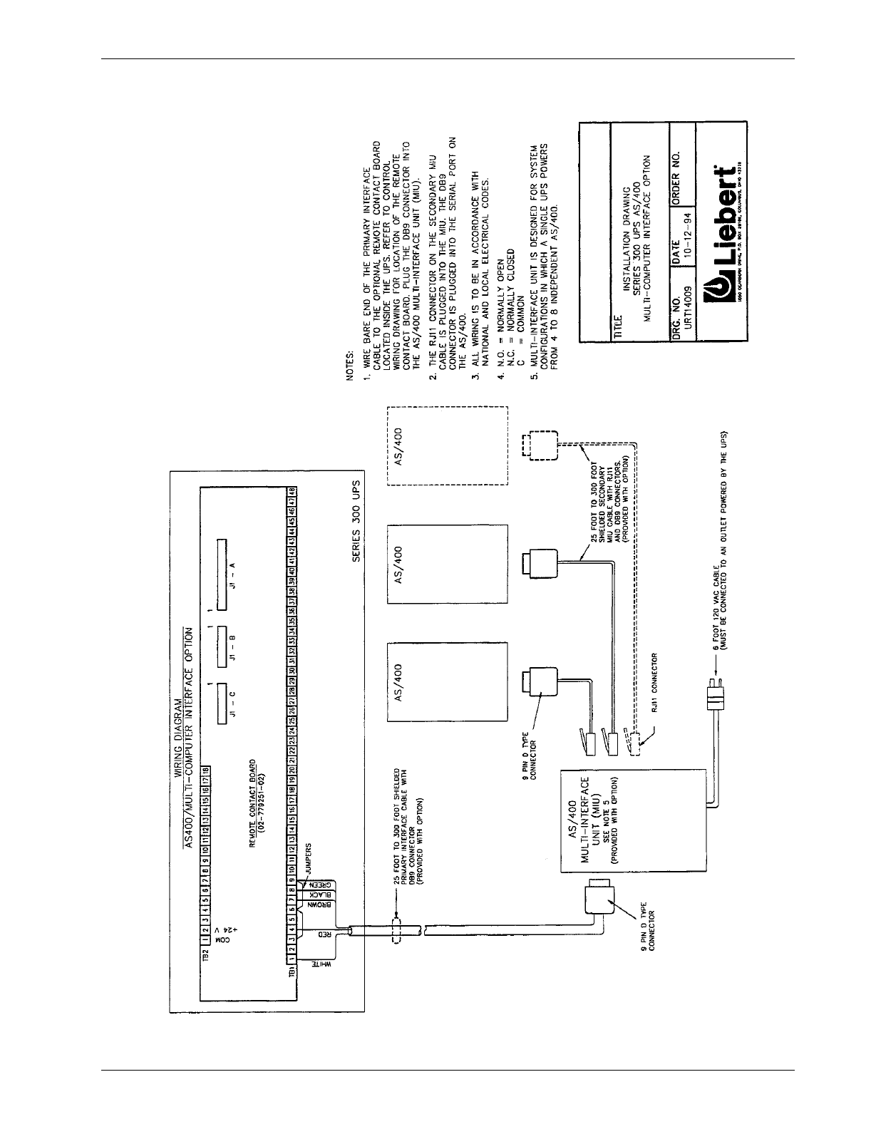
- 5.17 Optional IBM® AS/400 Multi-Interface System
- Figure 22 Optional Maintenance Bypass Cabinet
- Figure 23 Optional Maintenance Bypass Cabinet with Isolation Transformer
- Figure 24 Optional Slim-Line Distribution (continued)
- Figure 25 Optional Remote Status Panel
- Figure 26 Optional Remote Contact Board
- Figure 27 Optional IBM® AS/400 Signal Interface
- Figure 28 Optional IBM® AS/400 Signal Interface (with Remote Status Panel)
- Figure 29 Optional Battery Circuit Breaker 10-75 kVA
- Figure 30 Optional Battery Circuit Breaker 100-125 kVA
- Figure 31 Optional Computer Interface System
- Figure 32 Optional Multi-Computer Interface System
- Figure 33 Optional IBM® AS/400 Multi-Interface System
- 6.0 Specifications