Preface Thank you for choosing DELTA’s multi-function BLD-E1 Series. The BLD-E1 Series is manufactured with high-quality components and materials and incorporate the latest microprocessor technology available. This manual is to be used for the installation, parameter setting, troubleshooting, and daily maintenance of the brushless DC motor drive. To guarantee safe operation of the equipment, read the following safety guidelines before connecting power to the brushless DC motor drive.
WARNING! Never connect the output terminals U/T1, V/T2, and W/T3 of brushless DC motor drive directly to the AC mains circuit power supply. DO NOT use Hi-pot test for internal components. The semiconductor used in brushless DC motor drive easily damage by high-voltage. A charge may still remain in the DC-link capacitors with hazardous voltages, even if the power has been turned off.
Table of Contents Preface ............................................................................................................. i Table of Contents .......................................................................................... iii Chapter 1 Introduction ................................................................................ 1-1 1.1 Receiving and Inspection..................................................................... 1-2 1.1.1 Nameplate Information.......................
Chapter 3 Keypad and Start Up ..................................................................3-1 3.1 Keypad .................................................................................................3-2 3.2 Operation Method ................................................................................3-6 3.3 Trial Run ..............................................................................................3-8 Chapter 4 Parameters...............................................................
Chapter 1 Introduction| BLD-E1 Series 6.1.2 Reset .......................................................................................... 6-7 6.2 Maintenance and Inspections .............................................................. 6-7 Appendix A Specifications ........................................................................ A-1 Appendix B Accessories ........................................................................... B-1 B.
This page intentionally left blank
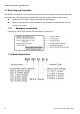
Chapter 1 Introduction The brushless DC motor drive should be kept in the shipping carton or crate before installation. In order to retain the warranty coverage, the brushless DC motor drive should be stored properly when it is not to be used for an extended period of time. Storage conditions are: CAUTION! 1. Store in a clean and dry location free from direct sunlight or corrosive fumes. 2. Store within an ambient temperature range of -20 °C to +60 °C. 3.
Chapter 1 Introduction|BLD-E1 Series 1.1 Receiving and Inspection This BLD-E1 brushless DC motor drive has gone through rigorous quality control tests at the factory before shipment. After receiving the brushless DC motor drive, please check for the following: Inspect the unit to assure it was not damaged during shipment. Make sure that the part number indicated on the nameplate corresponds with the part number of your order. 1.1.1 Nameplate Information Example for 1HP/0.
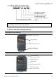
Chapter 1 Introduction| BLD-E1 Series 1.1.3 Series Number Explanation 007E123A 0T 9 14 0001 Pro du ction n um ber Pro du ction w eek Pro du ction year 2009 Pro du ction f act ory T: Taoyu an, W: Wu jian g 230V 3- ph ase 1HP (0.75kW ) Mo del If the nameplate information does not correspond to your purchase order or if there are any problems, please contact your distributor. 1.1.4 Drive Frames and Appearances 0.25-2HP/0.2-1.
Chapter 1 Introduction|BLD-E1 Series Internal Structure Digital keypad NPN/PNP ACI/AVI External terminals RS485 port (RJ-45) RFI Jumper Location NOTE The RFI jumper of frame A and frame B is beside the input terminals (R/L1, S/L2, T/L3) as circled in above picture and can be removed by loosening the screws. 1-4 Frame Power range A 0.25-2hp (0.2-1.5kW) B 1-5hp (0.75-3.
Chapter 1 Introduction| BLD-E1 Series RFI Jumper RFI Jumper: The brushless DC motor drive may emit the electrical noise. The EMI(electromagnetic interference with standard Y capacity) is used to suppress the interference (Radio Frequency Interference) on the power line. As the leakage current will be increased after using with EMI, user can cut off the RFI when reducing the leakage current is required.
Chapter 1 Introduction|BLD-E1 Series TN-S grounding system: TN-S is a grounding system with 3-phase, 4-line and PE line. The feature of TN-S system is the neutral line and protective earth(PE) line have an only common grounding at the neutral point of transformer. The neutral line (N) is live part and PE line is NOT live part. This grounding system equips safe and reliable basic potential.
Chapter 1 Introduction| BLD-E1 Series L1 L2 L3 N PE PEN L1 L2 L3 TN-C-S grounding system TT grounding system: TT grounding system is usually called 3-phase 4-line grounding system. The feature of TT grounding system is no electrical connection between the neutral line and protective earthing, i.e. the grounding of the neutral and PE line is separated. No matter 3-phase load is balanced or not, the PE line won’t be live part as the neutral line is live part when this system is in normal operation.
Chapter 1 Introduction|BLD-E1 Series 1.1.5 Remove Instructions Remove Front Cover Remove Fan For Frame A and Frame B, press and hold in the tabs on each side of the fan and pull the fan up to release. Step 1 Step 2 1.2 Preparation for Installation and Wiring 1.2.
Chapter 1 Introduction| BLD-E1 Series Minimum Mounting Clearances Frame A Mounting Clearances 1 20 mm 120mm 50mm 50mm 50mm 50mm Air Fl ow 1 20 mm 120mm single drive side-by-side installation air flow Frame B Mounting Clearances 150mm 1 50 mm 50mm 50mm 50mm 50mm Air Fl ow 150mm single drive 1 50 mm side-by-side installat ion air f low CAUTION! 1. Operating, storing or transporting the brushless DC motor drive outside these conditions may cause damage to the brushless DC motor drive.
Chapter 1 Introduction|BLD-E1 Series 5. The heat sink temperature may rise to 90°C when running. The material on which the brushless DC motor drive is mounted must be noncombustible and be able to withstand this high temperature. 6. When brushless DC motor drive is installed in a confined space (e.g. cabinet), the surrounding temperature must be within 10 ~ 40°C with good ventilation. DO NOT install the brushless DC motor drive in a space with bad ventilation. 7.
Chapter 1 Introduction| BLD-E1 Series NOTE Prevent fiber particles, scraps of paper, dust, metal particles from adhering to the heatsink. The material on which the brushless DC motor is mounted must be noncombustible and be able to withstand the high temperature to prevent fire accidents. The parallel connection of multiple drives is NOT for 115V models. Revision May 2009, 00DE, V0.
Chapter 1 Introduction|BLD-E1 Series 1.3 Dimensions (Dimensions are in millimeter and [inch]) Frame A D W W1 S1 H H1 D1 S2 Frame W W1 H H1 D D1 S1 S2 A 72.0 [2.83] 59.0 [2.32] 174.0 [6.86] 151.6 [5.97] 136.1 [5.36] 4.0 [0.16] 5.4 [0.21] 5.4 [0.21] B 100.0 [3.94] 89.0 [3.50] 174.0 [6.85] 162.9 [6.42] 136.0 [5.36] 4.0 [0.16] 5.9 [0.23] 5.4 [0.
Chapter 2 Installation and Wiring After removing the cover of input/output terminals and control terminals, check if terminals are clear. Be sure to observe the following precautions when wiring. CAUTION! 1. Make sure that power is only applied to the R/L1, S/L2, T/L3 terminals. Failure to comply may result in damage to the equipment. The voltage and current should lie within the range as indicated on the nameplate. 2.
Chapter 2 Installation and Wiring| BLD-E1 Series 2.1 Wiring There are main circuit and control circuit for the wiring of the brushless DC motor. Users must connect wires according to the circuit diagrams on the following pages. Figure 1 for models of BLD-E1 Series BLD002E111A/121A, BLD004E111A/121A, BLD007E111A/121A, BLD015E121A, BLD022E121A 2-2 Revision May 2009, 00DE, V0.
Chapter 2 Installation and Wiring| BLD-E1 Series Figure 2 for models of BLD-E1 Series BLD002E123A, BLD004E123A/143A, BLD007E123A/143A, BLD015E123A/143A, BLD022E123A/143A, BLD037E123A/143A Revision May 2009, 00DE, V0.
Chapter 2 Installation and Wiring| BLD-E1 Series Figure 3 Wiring for NPN mode and PNP mode NPN Mode Applicable Output Signal Factory setting is NPN Open collector output NP N VCC P NP Factory setting Multi-function input terminals O/P 0V NOTE It needs to connect O/P to multi-function input terminals for normal operation. NOTE Don't apply mains voltage into above terminals.
Chapter 2 Installation and Wiring| BLD-E1 Series 6. With long motor cables between the brushless DC motor drive and motor, high capacitive switching current peaks can cause over-current, high leakage current or lower current readout accuracy. To prevent this, the motor cable should be less than 20m for 3.7kW models and below. And the cable should be less than 50m for 5.5kW models and above. For longer motor cables use an AC output reactor. 7.
Chapter 2 Installation and Wiring| BLD-E1 Series 2.2 External Wiring Items Power supply Explanations Please follow the specific power supply requirements shown in Appendix A. There may be an inrush current during Fuse/NFB power up. Please check the chart of (Optional) Appendix B and select the correct fuse with rated current. Use of an NFB is optional. Do NOT run/stop brushless DC motor drives by turning the magnetic contactor ON/OFF, Magnetic as it will reduce the usage life of drive.
Chapter 2 Installation and Wiring| BLD-E1 Series 2.3 Main Circuit 2.3.1 Main Circuit Connection Terminal Symbol R/L1, S/L2, T/L3 U/T1, V/T2, W/T3 Explanation of Terminal Function Input terminals of commercial power (1-phase/3-phase) Output terminals of brushless DC motor drive for connecting brushless DC motor. Wire: U/T1 (Red); V/T2 (White); W/T3 (Black) +, E Connections for External Brake unit (BUE series) Earth connection, please comply with local regulations.
Chapter 2 Installation and Wiring| BLD-E1 Series When using a general GFCI (Ground Fault Circuit Interrupter), select a current sensor with sensitivity of 200mA or above, and not less than 0.1-second operation time to avoid nuisance tripping. For the specific GFCI of the brushless DC motor drive, please select a current sensor with sensitivity of 30mA or above. Output terminals for main circuit (U, V, W) The factory setting of the operation direction is forward running.
Chapter 2 Installation and Wiring| BLD-E1 Series 2.3.2 Main Circuit Terminals Frame A Main circuit terminals: R/L1, S/L2, T/L3, U/T1, V/T2, W/T3, Models Wire BLD002E111A BLD002E121A , +, Torque Wire type 14-16 kgf-cm (12-14 in-lbf) Stranded copper Only, 75℃ BLD002E123A BLD004E111A BLD004E121A BLD004E123A BLD004E143A BLD007E121A BLD007E123A BLD007E143A BLD015E123A BLD015E143A Frame B 12-18 AWG (3.30.
Chapter 2 Installation and Wiring| BLD-E1 Series 2.4 Control Terminals Specification Torque Wire Terminal A, B 2 kgf-cm (2 in-lbf) 16-24 AWG (1.3-0.2mm2) Terminal symbols and functions Terminal Symbol 2-10 Factory Settings (NPN mode) Terminal Function ON: Connect to DCM ON: forward running OFF: Ramp to stop ON: reverse running OFF: Ramp to stop MI1 Forward-Stop command MI2 Reverse-Stop command MI3 Multi-function Input 3 Refer to Pr.04-05 to Pr.
Chapter 2 Installation and Wiring| BLD-E1 Series Terminal Symbol Factory Settings (NPN mode) Terminal Function ON: Connect to DCM +24V DC Voltage Source +24VDC, 20mA DCM Digital Signal Common Common for digital inputs HU/U Reserved HV/V Reserved HW/W Reserved A PG feedback signal contact 1 B PG feedback signal contact 2 Z/PWM Sending PG signals to the drive, e.g. activation, operation, speed control etc. Sending PG signals to the drive, e.g. activation, operation, speed control etc.
Chapter 2 Installation and Wiring| BLD-E1 Series Terminal Factory Settings (NPN mode) Terminal Function Symbol ON: Connect to DCM Analog voltage Input +10V AVI AVI Impedance: 20kΩ Resolution: 10 bits Range: 0 ~ 10VDC = 0 ~ Max. Output Speed (Pr.01-00) ACM internal circuit Analog current Input ACI ACI DC Impedance: 250Ω/100kΩ Resolution: 10 bits Range: 4 ~ 20mA = 0 ~ Max. Output Speed(Pr.
Chapter 2 Installation and Wiring| BLD-E1 Series Digital inputs (MI1~MI6, DCM) When using contacts to control the digital inputs, please use high quality components to avoid contact bounce. Digital outputs (MO1, MO2, MCM) Make sure to connect the digital outputs to the right polarity, see wiring diagrams. When connecting a relay to the digital outputs, connect a surge absorber or fly-back diode across the coil and check the polarity. Revision May 2009, 00DE, V0.
Chapter 2 Installation and Wiring| BLD-E1 Series This page intentionally left blank 2-14 Revision May 2009, 00DE, V0.
Chapter 3 Keypad and Start Up 3.1 Keypad 3.2 Operation Method 3.3 Trial Run Make sure that the wiring is correct. In particular, check that the output terminals U/T1, V/T2, W/T3 are NOT connected to power and that the drive is well grounded. Verify that no other equipment is connected to the motor. Do NOT operate the brushless DC motor drive with humid hands. Check if it displays 2000.0 on the digital keypad after power is applied.
Chapter 3 Keypad and Start Up| BLD-E1 Series 3.1 Keypad 3 1 2 4 5 6 7 1 Status Display Disp la y t he driv er' s operat ion sta tus. 2 LED Displ ay In dicat e s pee d, volta ge, cu rre nt a nd user de fined units. 3 Potentiometer For mas te r sp eed set ting . 8 5 UP and DO WN K ey Se t t he pa ramete r numbe r and cha nge t he nume ric al da ta, su ch as master spe ed. 6 MODE Chan ge be tween diff erent disp la y mode.
Chapter 3 Keypad and Start Up| BLD-E1 Series Display Message Descriptions Displays the master speed of the drive and RPM signal blinking. Displays the actual output speed at terminals U/T1, V/T2, and W/T3. User defined unit Displays the output current at terminals U/T1, V/T2, and W/T3. Displays the brushless DC motor drive forward run status. Displays the brushless DC motor drive reverse run status. The counter value (C). Speed is controlled by current setting.
Chapter 3 Keypad and Start Up| BLD-E1 Series 3.1.1 How to Operate the Digital Keypad The setting values in the following diagram are only example. Please regards the setting value according to BLD-E1 Series. 3-4 Revision May 2009, 00DE, V0.
Chapter 3 Keypad and Start Up| BLD-E1 Series Reference Table for the 7-segment LED Display of the Digital Keypad Digit LED Display ASCII Digit LED Display ASCII Digit LED Display ASCII Digit LED Display ASCII Digit 0 1 5 6 7 8 9 0x33 0x34 d E 0x35 F 0x36 G 0x37 Hh 0x38 i 0x39 Jj 0x41 0x62 0x43,0x63 0x64 0x45 K L n o P 0x46 q 0x47 0x48,0x68 r S 0x69 0x4a,0x6a t Uu 0x4b 0x4c v Y 0x6e Z 0x71 0x72 0x53 0x74 0x55,0x75 0x76 0x59 0x5a F﹒ G﹒ H﹒h﹒ 0x30 0x31 A b A﹒ b﹒ 2 0x32 Cc C﹒c﹒
Chapter 3 Keypad and Start Up| BLD-E1 Series 3.2 Operation Method The operation method can be set via communication and control terminals. Operation Method Operate from the communication Frequency Source Operation Command Source When setting communication by the PC, it needs to use VFD-USB01 or IFD8500 converter to connect to the PC. Refer to the communication address 2000H and 2101H setting for details.
Chapter 3 Keypad and Start Up| BLD-E1 Series Operation Method Operation Command Source Frequency Source +24V F WD /Stop F ac tor y s etting: NPN Mode NPN R EV/Stop Multi-s tep 1 F ac tor y setting Multi-s tep 2 PNP Multi-s tep 3 Multi-s tep 4 Digital Si gnal Common * Don't apply the mains voltage directly to abov e terminals.
Chapter 3 Keypad and Start Up| BLD-E1 Series 3.3 Trial Run The factory setting of trial run is by the potentiometer, please operate by the following steps. 1. After applying the power, setting the parameter according to the motor type in parameter group 08. (For Delta’s ECMD-E9 Series of motor, the drive will atuo set the motor parameter to the default value) 2. Please execute angle detection for the first time operation of Delta ECMD-E9 Motor and drive.
Chapter 4 Parameters The BLD-E1 parameters are divided into 14 groups by property for easy setting. In most applications, the user can finish all parameter settings before start-up without the need for re-adjustment during operation. 4.1 Summary of Parameter Setting 4.
Chapter 4 ParametersAT |Troubleshooting}| BLD-E1 Series 4.1 Summary of Parameter Settings Group 00 System Parameters Parameter 00.00 Explanation Identity Code of : The parameter can be set during operation. Settings 0:115V,1PH,0.2KW,1/4HP the Brushless DC 2:115V,1PH,0.4KW,1/2HP Motor Drive Factory Setting Read- VF VFPG FOCPM ○ ○ ○ ○ ○ ○ only 4:115V,1PH,0.7KW,1HP 0:230V,1PH,0.2KW,1/4HP 2:230V,1PH,0.4KW,1/2HP 4:230V,1PH,0.7KW,1HP 6:230V,1PH,1.5KW,2HP 8:230V,1PH,2.2KW,3HP 0:230V,3PH,0.
Chapter 4 Parameters| BLD-E1 Series Parameter Explanation Settings Factory Setting VF VFPG FOCPM 5:defined by user (Pr.00-04) 00.04 Content of Multi- 0:Display the output current from 0 function Display drive to motor ○ ○ ○ 1:Reserved 2:Display actual output frequency 3:Display DC-Bus voltage (U) 4:Display output voltage of U, V, W (E) 5:Display output power factor angle (n.
Chapter 4 ParametersAT |Troubleshooting}| BLD-E1 Series Parameter Explanation Settings Factory Setting VF VFPG FOCPM malfunction 25:Output DC voltage when malfunction 26:Motor frequency when malfunction 27:Output current when malfunction 28:Output frequency when malfunction 29:Frequency command when malfunction 30:Output power when malfunction 31:Output torque when malfunction 32:Input terminal status when malfunction 33:Output terminal status when malfunction 34:Drive status when malfunction 00.
Chapter 4 Parameters| BLD-E1 Series Parameter Explanation Settings Factory Setting VF VFPG FOCPM Regulation (AVR) 1:Disable AVR 2:Disable AVR when deceleration stop 00.14 Source of 0:Digital keypad input Frequency 1:RS-485 serial communication Command input 2 ○ ○ ○ 0 ○ ○ ○ 2:External analog input (Pr.03-00~03-02) 3:Digital terminals input (Pr.04-00~04-15) 00.
Chapter 4 ParametersAT |Troubleshooting}| BLD-E1 Series Group 01 Basic Parameters Parameter 01.00 Explanation Maximum Operation : The parameter can be set during operation. Settings 120~4000RPM (10~400Hz) Frequency 01.01 1st Output Factory Setting 3000 VF VFPG FOCPM ○ ○ ○ (250) 0~400.00Hz 60.00 ○ ○ ○ 1st Output Voltage 230V Series:0.0V~255.0V 220.0 ○ ○ ○ Setting 1 460V Series:0.0V~510.0V 440.0 0~400.00Hz 0.50 ○ ○ 2nd Output Voltage 230V Series:0.0V~255.0V 5.
Chapter 4 Parameters| BLD-E1 Series Parameter Explanation Settings Factory Setting VF VFPG FOCPM 01.18 Accel Time 4 0.00~600.00 sec 3.00 ○ ○ ○ 01.19 Decel Time 4 0.00~600.00 sec 2.00 ○ ○ ○ 01.20 Reserved 01.21 Reserved 01.22 Reserved 01.23 Switch Frequency 0~4000rpm (0~400.00Hz) 0 (0.00) ○ ○ ○ 0.0~25.0 sec 0.0 ○ ○ ○ 0.0~25.0 sec 0.0 ○ ○ ○ 0.0~25.0 sec 0.0 ○ ○ ○ 0.0~25.0 sec 0.0 ○ ○ ○ 0 ○ ○ 0~4000rpm (0~400.00Hz) 0 (0.00) ○ ○ ○ 0.0~25.0 sec 0.
Chapter 4 ParametersAT |Troubleshooting}| BLD-E1 Series Group 02 Digital Parameter : The parameter can be set during operation. Explanation Settings Factory Setting VF VFPG FOCPM 0:2-wire operation mode1, 02.
Chapter 4 Parameters| BLD-E1 Series Parameter Explanation Settings Factory VF VFPG FOCPM 13~14: Reserved ○ ○ ○ 15:Running speed ○ ○ ○ ○ ○ ○ ○ ○ ○ ○ ○ ○ 19~26:Reserved ○ ○ ○ 27:ASR1/ASR2 Selection ○ ○ ○ 28:Emergency stop (EF1) ○ ○ ○ 29~30:Reserved ○ ○ ○ 31: High torque bias (by ○ ○ ○ ○ ○ ○ ○ ○ ○ 34-37: Reserved ○ ○ ○ 38: Disable EEPROM write ○ ○ ○ 39:Reserved ○ ○ ○ 40:Enable drive to ○ ○ ○ Setting command from VR 16:Running speed command fro
Chapter 4 ParametersAT |Troubleshooting}| BLD-E1 Series Parameter Explanation Settings Factory VF VFPG FOCPM Setting 02.12 02.13 Reserved 0:No function 41 ○ ○ ○ Multi-function 1: Operation indication 41 ○ ○ ○ Output (MO2) 2: Operation speed attained ○ ○ ○ 3:Desired frequency ○ ○ ○ ○ ○ ○ ○ ○ ○ ○ ○ ○ ○ ○ ○ ○ ○ ○ 9: Drive ready ○ ○ ○ 10:Low-voltage Detection ○ ○ ○ 11:Malfunction indication ○ ○ ○ 12:Reserved ○ ○ ○ 13:Overheat warning (Pr.
Chapter 4 Parameters| BLD-E1 Series Parameter Explanation Settings Factory VF VFPG FOCPM ○ ○ ○ ○ ○ ○ 27~30:Reserved ○ ○ ○ 31:Forward running input ○ ○ ○ 32:Reverse running input ○ ○ ○ 33:Zero-speed (Actual output frequency) ○ ○ ○ 34:Zero speed with Stop ○ ○ ○ 35~39:Reserved ○ ○ ○ 40:Speed attained ○ ○ ○ Setting 25: Forward running command 26: Reverse running command (actual output frequency) (including zero speed) 02.
Chapter 4 ParametersAT |Troubleshooting}| BLD-E1 Series Group 03: Time Parameters Parameter Explanation : The parameter can be set during operation. Settings Factory Setting VF VFPG FOCPM 03.00 Analog Input (VR) 0:No function 1 ○ ○ ○ 03.01 Analog Input (ACI) 1:Frequency command (torque limit 0 ○ ○ ○ ○ ○ ○ under TQR control mode) 03.02 Analog Input 3 2:Reserved (AVI) 3: Preload input 0 4~6:Reserved 03.
Chapter 4 Parameters| BLD-E1 Series Parameter 03.13 Explanation Settings Analog Input Delay 0.00~2.00 sec Factory Setting VF VFPG FOCPM 0.05 ○ ○ ○ 0.05 ○ ○ ○ 0 ○ ○ ○ Time ACI 03.14 Analog Input Delay 0.00~2.00 sec Time AVI 03.15 Loss of the ACI 0: Disable Signal 1: Continue operation at the last frequency 2: Decelerate to 0Hz 3: Stop immediately and display E.F. Revision May 2009, 00DE, V0.
Chapter 4 ParametersAT |Troubleshooting}| BLD-E1 Series Group 04: Multi-Step Speed Parameters : The parameter can be set during operation. Parameter 04.00 Explanation Zero Step Speed Settings Factory Setting VF VFPG FOCPM 0~4000RPM (0.00~400.0Hz) 0.00 ○ ○ ○ 0~4000RPM (0.00~400.0Hz) 0.00 ○ ○ ○ 0~4000RPM (0.00~400.0Hz) 0.00 ○ ○ ○ 0~4000RPM (0.00~400.0Hz) 0.00 ○ ○ ○ 0~4000RPM (0.00~400.0Hz) 0.00 ○ ○ ○ 0~4000RPM (0.00~400.0Hz) 0.00 ○ ○ ○ 0~4000RPM (0.00~400.0Hz) 0.
Chapter 4 Parameters| BLD-E1 Series Group 05: IM Parameters Parameter 05.18 Explanation Accumulative : The parameter can be set during operation. Settings Factory Setting VF VFPG FOCPM 00~1439 0 ○ ○ ○ 00~65535 0 ○ ○ ○ 00~1439 0 ○ ○ ○ 00~65535 0 ○ ○ ○ Motor Operation Time (min.) 05.19 Accumulative Motor Operation Time (day) 05.21 Accumulative Drive Power-on Time (min.) 05.22 Accumulative Drive Power-on Time (day) Revision May 2009, 00DE, V0.
Chapter 4 ParametersAT |Troubleshooting}| BLD-E1 Series Group 6: Protection Parameters Parameter 06.00 06.01 Explanation Low Voltage Level : The parameter can be set during operation. Settings Factory Setting 160.0~220.0Vdc 180.0 320.0~440.0Vdc 360.0 Phase-loss 0: Warn and keep operation Protection 1: Warn and ramp to stop VF VFPG FOCPM ○ ○ ○ 2 ○ ○ ○ 00 ○ ○ 00 ○ ○ 0 ○ ○ 0 ○ ○ ○ 10~250% 150 ○ ○ ○ 0.0~60.0 sec 0.1 ○ ○ ○ 2: Warn and coast to stop 06.
Chapter 4 Parameters| BLD-E1 Series Parameter Explanation Settings Factory Setting VF VFPG FOCPM Detection Time (OT1) 06.08 Over-torque 0: disable 0 ○ ○ ○ 10~250% 150 ○ ○ ○ 0.0~60.0 sec 0.1 ○ ○ ○ 0~250% 200 ○ ○ ○ 2 ○ ○ ○ 60.0 ○ ○ ○ 85.0 ○ ○ ○ 0~100% (refers to Pr.
Chapter 4 ParametersAT |Troubleshooting}| BLD-E1 Series Parameter Explanation Recent Fault Settings Factory Setting VF VFPG FOCPM (ocA) Record 06.18 06.19 06.20 Third Most Recent 2: Over-current during deceleration Fault Record (ocd) Fourth Most Recent 3: Over-current during constant 0 ○ ○ ○ 0 ○ ○ ○ Fault Record speed (ocn) Fifth Most Recent 4: Ground fault (GFF) 0 ○ ○ ○ Sixth Most Recent 5:Reserved 0 ○ ○ ○ Fault Record 6: Over-current at stop (ocS) Fault Record 06.
Chapter 4 Parameters| BLD-E1 Series Parameter Explanation Settings Factory Setting VF VFPG FOCPM 29: Reserved 30: Memory write-in error (cF1) 31: Memory read-out error (cF2) 32: Isum current detection error (cd0) 33: U-phase current detection error (cd1) 34: V-phase current detection error (cd2) 35: W-phase current detection error (cd3) 36:current detection error (Hd0) 37:current detection error (Hd1) 38:Over-voltage detection error (Hd2) 39: Ground current detection error (Hd3) 40: Auto tuning error
Chapter 4 ParametersAT |Troubleshooting}| BLD-E1 Series Group 07 Protection Parameters Parameter Explanation 07.00 Reserved 07.01 Reserved 07.02 DC Brake : The parameter can be set during operation. Settings Factory Setting VF VFPG FOCPM 0~100% 0 ○ ○ 0.0~60.0 sec 0.0 ○ ○ ○ 0.0~60.0 sec 0.0 ○ ○ ○ 0~4000rpm (0.00~400.0Hz) 0.00 ○ ○ 1~500 50 ○ ○ 0: Fan always ON 1 ○ ○ Current Level 07.03 DC Brake Time during Start-up 07.04 DC Brake Time during Stopping 07.
Chapter 4 Parameters| BLD-E1 Series Parameter Explanation Settings Factory VF VFPG FOCPM Setting 07.19 Source of 0: Disable Torque Offset 1: Analog input (Pr.03- 0 ○ 0.0~100.0% 0.0 ○ 0.0~100.0% 30.0 ○ 0.0~100.0% 20.0 ○ 0.0~100.0% 10.0 ○ 0~300% 200 ○ 0~300% 200 ○ 0~300% 200 ○ 0~300% 200 ○ Emergency 0: Coast to stop 0 Stop (EF) & 1: By deceleration Time 1 Forced Stop 2: By deceleration Time 2 Selection 3: By deceleration Time 3 00) 2: Torque offset setting (Pr.
Chapter 4 ParametersAT |Troubleshooting}| BLD-E1 Series Group 08 PM Parameters Parameter 08.00 Explanation : The parameter can be set during operation. Settings Motor Auto 0: No function Tuning 1: Only for the unloaded motor, auto Factory Setting VF VFPG FOCPM 0 ○ #.## ○ 0.00~655.35kW #.## ○ 0~65535 200 ○ 10 ○ 0.000~65.535Ω # ○ measure the angle between magnetic pole and PG origin (Pr. 08.09) 2: For PM parameters 3: Auto measure the angle between magnetic pole and PG origin (Pr.
Chapter 4 Parameters| BLD-E1 Series Group 09 Communication Parameters Parameter 09.00 Explanation Communication : The parameter can be set during operation. Settings 1~254 Factory Setting VF VFPG FOCPM 1 ○ ○ ○ 9.6 ○ ○ ○ 3 ○ ○ ○ 0.0~100.0 sec 0.0 ○ ○ ○ Communication 0: 7N1 (ASCII) 1 ○ ○ ○ Protocol (Keypad) 1: 7N2 (ASCII) 2.0 ○ ○ ○ Address 09.01 Transmission Speed 4.8~38.4Kbps (Keypad) 09.
Chapter 4 ParametersAT |Troubleshooting}| BLD-E1 Series Group 10: Speed Feedback Control Parameters : The parameter can be set during operation. Parameter 10.00 Explanation Encoder Type Settings 0:No function Factory Setting VF VFPG FOCPM 3 ○ ○ 1:ABZ 2:ABZ+UVW 3:AB+PWM 10.01 Encoder Pulse 1~25000 256 ○ ○ 10.
Chapter 4 Parameters| BLD-E1 Series Parameter 10.09 Explanation Settings Encoder Stall and Slip 0: Warn and keep operation Error Treatment Factory Setting VF VFPG FOCPM 2 ○ 0 ○ ○ 1: Warn and decelerate to stop 2: Warn and stop operation 10.10 Mode Selection for 0: Z signal is at the falling edge UVW Input of U-phase 1: Z signal is at the rising edge of U-phase 10.11 ASR (Auto Speed 0.0~500.0% 100.0 ○ ○ ○ 0.000~10.000 sec 0.200 ○ ○ ○ 0.0~500.0% 100.0 ○ ○ ○ 0.000~10.
Chapter 4 ParametersAT |Troubleshooting}| BLD-E1 Series Parameter Explanation Settings Factory Setting VF VFPG FOCPM Width Adjustment 10.21 ASR1/ASR2 Width 0~4000RPM (0.00~400.0Hz) 5.00 0.000~65.535 sec 0.250 ○ 0.000~65.535 sec 0.004 ○ ○ ○ Adjustment 10.22 Operation Time of Zero Speed 10.23 Filter Time of Zero Speed 4-26 Revision May 2009, 00DE, V0.
Chapter 4 Parameters| BLD-E1 Series Group 11: Advanced Parameters Parameter 11.00 Explanation System Control : The parameter can be set during operation. Settings bit 7=1:Enable position control Factory Setting 0 VF VFPG FOCPM ○ ○ ○ bit 15=0:when power is applied,it will re-detect the magnetic pole position 11.01 ~ 11.05 11.06 Reserved Zero-speed 0~40Hz 10 ○ 0~40Hz 10 ○ 0~40Hz 10 ○ Bandwidth 11.07 Low-speed Bandwidth 11.08 High-speed Bandwidth 11.09 ~ Reserved 11.15 11.
Chapter 4 ParametersAT |Troubleshooting}| BLD-E1 Series Group 12: User-defined Parameters (User-defined Parameters: from group 00 to 11) Parameter 12.00 Explanation Present Fault Settings : The parameter can be set during operation. Factory Setting 0616 Read-only 0632 Read-only Record 12.01 Present Fault Time of Motor VF VFPG FOCPM ○ ○ ○ ○ ○ ○ ○ ○ ○ ○ ○ ○ ○ ○ ○ ○ ○ ○ ○ ○ ○ ○ ○ ○ ○ ○ ○ ○ ○ ○ ○ ○ ○ ○ ○ ○ ○ ○ ○ Operation (min.) 12.
Chapter 4 Parameters| BLD-E1 Series Parameter 12.13 Explanation Multi-function Settings 2142 Terminal Factory Setting Read- VF VFPG FOCPM ○ ○ ○ ○ ○ ○ ○ ○ ○ ○ ○ ○ ○ ○ ○ ○ ○ ○ ○ ○ ○ ○ ○ ○ only Output Status at Present Fault 12.14 Drive Status at 2143 Present Fault 12.15 Second Most Readonly 0617 Recent Fault Readonly Record 12.16 Second Most 0634 Recent Fault Readonly Time of Motor Operation (min.) 12.
Chapter 4 ParametersAT |Troubleshooting}| BLD-E1 Series Parameter 12.21 Explanation Fourth Most Settings 0619 Recent Fault Factory Setting Read- VF VFPG FOCPM ○ ○ ○ ○ ○ ○ ○ ○ ○ ○ ○ ○ ○ ○ ○ ○ ○ ○ ○ ○ ○ ○ ○ ○ only Record 12.22 Fourth Most 0638 Recent Fault Readonly Time of Motor Operation (min.) 12.23 Fourth Most 0639 Recent Fault Readonly Time of Motor Operation (day) 12.24 Fifth Most 0620 Recent Fault Readonly Record 12.
Chapter 4 Parameters| BLD-E1 Series Parameter Explanation Settings Factory Setting VF VFPG FOCPM ○ ○ ○ ○ ○ ○ ○ ○ ○ Operation (min.) 12.29 Sixth Most Recent Fault 0643 Readonly Time of Motor Operation (day) 12.30 No Factory Setting 12.31 No Factory Setting Revision May 2009, 00DE, V0.
Chapter 4 ParametersAT |Troubleshooting}| BLD-E1 Series Group 13: View User-defined Parameters : The parameter can be set during operation. Parameter Explanation 13.00 ~ View User-defined 13.31 Parameters 4-32 Settings Pr. 00-00~11-16 Factory Setting VF VFPG FOCPM ○ ○ ○ Revision May 2009, 00DE, V0.
Chapter 4 Parameters| BLD-E1 Series 4.2 Description of Parameter Settings Group 00 User Parameters : This parameter can be set during operation. Identity Code of the Brushless DC Motor Drive 00-00 Control mode VF VFPG Settings Factory setting: Read Only FOCPM Read Only Rated Current Display of the Brushless DC Motor Drive 00-01 Control mode VF VFPG Settings Factory setting: Read Only FCPM Read Only Pr. 00-00 determines the drive capacity that is set by the factory.
Chapter 4 ParametersAT |Troubleshooting}| BLD-E1 Series 00-02 Parameter Reset Control VF mode VFPG Settings 0 Factory setting: 0 FOCPM No Function 10 All parameters are reset to factory settings When it is set to 10, all parameters will be reset to factory settings. 00-03 Start-up Display Selection Control VF mode VFPG Settings 0 Factory setting: 0 FOCPM Display the frequency command value.
Chapter 4 Parameters| BLD-E1 Series Content of Multi-Function Display 00-04 10 Display the electrical angle of drive output 11 12 13 Display the signal of VR analog input terminal in %. Range 0~10V corresponds to 0~100%. Display the signal of ACI analog input terminal in %. Range 4~20mA/0~10V corresponds to 0~100%. Display the signal of AVI analog input terminal in %. Range -10V~10V corresponds to 0~100%. 14 Reserved 15 Display the temperature of IGBT in °C.
Chapter 4 ParametersAT |Troubleshooting}| BLD-E1 Series 0: OFF, 1: ON MI3: Pr.02-01 is set to 1 (multi-step speed command 1) MI6: Pr.02-04 is set to 8 (the 1st, 2nd acceleration/deceleration time selection) If REV, MI2, MI3 and MI6 are ON, the value is 0000 0000 0010 0110B in binary and 0026H in HEX. At the meanwhile, if Pr.00-04 is set to “16” or “19”, it will display “0026” with LED U is ON on the keypad KPVL-CC01.
Chapter 4 Parameters| BLD-E1 Series Ramp to stop: the brushless DC decelerates the motor to Minimum Output Frequency Pr.01-09 and stops according to the deceleration time set in Pr.01-07. Coast to stop: the brushless DC drive stops output instantly upon command, and motor free run until it comes to a complete stop. If the machinery is turned off, the motor must also be stopped to avoid waste of power and for safety concern.
Chapter 4 ParametersAT |Troubleshooting}| BLD-E1 Series This parameter determines the control method of the brushless DC motor drive: Setting 0: user can design V/f ratio by requirement and control multiple motors simultaneously. Setting 1: User can use PG card with Encoder to do close-loop speed control. Setting 8: To increase torque and control speed precisely. (1:1000). This setting is only for using with permanent magnet motor and others are for induction motor.
Chapter 4 Parameters| BLD-E1 Series temperature, carrier frequency will be lowered to 10kHz, moreover, overload condition will be adjust, e.g. Fc= 15kHz, rated output current= 50% * 55% = 82.5% and continues for 1 minute, the carrier frequency (Fc) will be reduced to the default setting.
Chapter 4 ParametersAT |Troubleshooting}| BLD-E1 Series 2K (Pr. 00-12 = 2) 900rpm 3K (Pr. 00-12 = 3) 1350rpm 4K (Pr. 00-12 = 4) 1800rpm 5K (Pr. 00-12 = 5) 2250rpm 6K (Pr. 00-12 = 6) 2700rpm Greater than 7K (Pr. 00-12 >7K) 3000rpm 00-13 Auto Voltage Regulation (AVR) Function Control mode VF Settings VFPG FOCPM 0 Enable AVR 1 Disable AVR 2 Disable AVR when deceleration Factory setting: 0 It is used to select the AVR mode. AVR is used to regulate the output voltage to the motor.
Chapter 4 Parameters| BLD-E1 Series BLE-E1 series is shipped without digital keypad and users can use external terminals or RS485 to control the operation command. When the LED PU is light, the operation command can be controlled by the optional digital keypad (KPC-CE01). Refer to appendix B for details. Revision May 2009, 00DE, V0.
Chapter 4 ParametersAT |Troubleshooting}| BLD-E1 Series Group 01 Basic Parameters This parameter can be set during operation. Maximum Output Frequency 01-00 Control mode VF VFPG Settings FOCPM Factory setting: 3000(250) 120~4000rpm (10~400z) This parameter determines the brushless DC motor drive’s Maximum Output Frequency. All the brushless DC motor drive frequency command sources (analog frequency inputs 0 to +10V and 4 to 20mA) are scaled to correspond to the output frequency range.
Chapter 4 Parameters| BLD-E1 Series 01-03 Control mode 2nd Output Frequency Setting VF Settings 01-04 Control mode Control mode VF Control mode VF Control mode VF Control mode 0.1 to 255.0V Factory Setting: 5.0 460V series 0.1 to 510.0V Factory Setting: 10.0 Factory setting: 0.50 VFPG 0.00~400.00Hz VFPG 230V series 0.1 to 255.0V Factory Setting: 5.0 460V series 0.1 to 510.0V Factory Setting: 10.
Chapter 4 ParametersAT |Troubleshooting}| BLD-E1 Series Voltage Output Frequency Output Frequency 1st Output Upper Limit 01-10 Voltage Setting 1 01-11 Lower Limit 01-02 Frequency output 2nd Output ranges limitation Voltage Setting 1 01-04 Regular V/f Curve 3rd Output Special V/f Curve Voltage Setting 1 01-06 4th Output Voltage Setting 1 01-08 01-07 01-09 01-05 01-03 01-01 1st Freq. 3rd Freq. 4th Freq. 2nd Freq. Start Freq.
Chapter 4 Parameters| BLD-E1 Series 01-12 Accel. Time 1 Factory setting: 3.00 01-14 Accel. Time 2 Factory setting: 3.00 01-16 Accel. Time 3 Factory setting: 3.00 01-18 Accel. Time 4 Factory setting: 3.00 Control mode VF VFPG Settings FOCPM 0.00~600.00 sec 01-13 Decel. Time 1 Factory setting: 2.00 01-15 Decel. Time 2 Factory setting: 2.00 01-17 Decel. Time 3 Factory setting: 2.00 01-19 Decel. Time 4 Factory setting: 2.00 Control mode VF VFPG Settings FOCPM 0.00~600.
Chapter 4 ParametersAT |Troubleshooting}| BLD-E1 Series Switch Frequency between 1st/4th Accel/decel 01-23 Control mode VF Settings VFPG Factory setting: 0 FOCPM 0.00~400.00Hz This parameter selects the frequency point for transition from acceleration/deceleration time 1 to acceleration/deceleration time 4. The transition from acceleration/deceleration time 1 to acceleration/deceleration time 4, may also be enabled by the external terminals. The external terminal has priority over Pr. 01-23.
Chapter 4 Parameters| BLD-E1 Series F requenc y 01-25=S2 01-26=S3 01-13 decel. time 01-12 accel. time 01-27=S4 01-24=S1 01-29 Switch fr equency for S3/S 4 changes to S5 Time 01-30=S5 Mode Selection when Frequency< Fmin 01-28 Control mode VF Settings VFPG SVC 0 Output Waiting 1 Zero-speed operation 2 Fmin (4th output frequency setting) Factory setting: 0 When the Brushless DC motor drive is at 0rpm, it will operate by this parameter.
Chapter 4 ParametersAT |Troubleshooting}| BLD-E1 Series Group 2 Digital Input/Output Parameters This parameter can be set during operation. 2-wire/3-wire Operation Control 02-00 Control mode VF VFPG Settings Factory setting: 0 FOCPM 0 FWD/STOP, REV/STOP 1 FWD/STOP, REV/STOP (Line Start Lockout) 2 RUN/STOP, REV/FWD 3 RUN/STOP, REV/FWD (Line Start Lockout) 4 3-wire 5 3-wire (Line Start Lockout) Three of the six methods include a “Line Start Lockout” feature.
Chapter 4 Parameters| BLD-E1 Series 02-01 Multi-Function Input Command 3 (MI3) Factory Setting: 1 02-02 Multi-Function Input Command 4 (MI4) Factory Setting: 2 02-03 Multi-Function Input Command 5 (MI5) Factory Setting: 3 02-04 Multi-Function Input Command 6 (MI6) Factory Setting: 4 Settings VF VFPG FOCPM 0:no function ○ ○ ○ 1:Multi-step command 1 ○ ○ ○ 2:Multi-step command 2 ○ ○ ○ 3:Multi-step command 3 ○ ○ ○ 4:Multi-step command 4 ○ ○ ○ 5:Reset ○ ○ ○ 7:acceleration/dece
Chapter 4 ParametersAT |Troubleshooting}| BLD-E1 Series Settings 33: Low torque bias (by Pr.07-23) VF VFPG FOCPM ○ ○ ○ ○ ○ ○ ○ ○ ○ 34-37: Reserved 38: Disable EEPROM write function 39:Reserved 40:Enable drive to function This parameter selects the functions for each multi-function terminal. If Pr.02-00 is set to 3-wire operation control. Terminal MI1 is for STOP terminal. Therefore, MI1 is not allowed for any other operation.
Chapter 4 Parameters| BLD-E1 Series Settings Functions Descriptions The acceleration/deceleration time of the drive could be selected from this function or the digital statuses of the terminals; there are 4 acceleration/deceleration speeds in total for selection. 8 The 1st, 2nd acceleration or deceleration time selection Bit 0 Bit Descriptions 1 0 0 First acceleration/deceleration time When output frequency is less than Pr.
Chapter 4 ParametersAT |Troubleshooting}| BLD-E1 Series Settings Functions 27 ASR1/ASR2 selection 28 Emergency stop (EF1) (Motor coasts to stop) 29-30 Descriptions ON: speed will be adjusted by ASR 2 setting. OFF: speed will be adjusted by ASR 1 setting. When it is ON, the drive will execute emergency stop with fault code 50 (EF1) Reserved 31 High torque bias 32 Middle torque bias When Pr.07-19 is set to 3: 31: The high torque bias is according to the Pr.07-21 setting.
Chapter 4 Parameters| BLD-E1 Series 02-09 Digital Input Response Time Control mode VF VFPG Settings Factory setting: 0.005 FOCPM 0.001~ 30.000 sec This parameter is used for digital input terminal signal delay and confirmation. The delay time is confirmation time to prevent some uncertain interferences that would result in error (except for the counter input) in the input of the digital terminals (FWD, REV and MI1~6).
Chapter 4 ParametersAT |Troubleshooting}| BLD-E1 Series 3:Desired frequency attained 1 (Pr. 02-25, 02-26) ○ ○ ○ 4:Desired frequency attained 2 (Pr. 02-27, 02-28) ○ ○ ○ 5: Zero speed (frequency command) ○ ○ ○ 6: Zero speed with stop (frequency command) ○ ○ ○ 7: Over torque (OT1) ○ ○ ○ 8: Over torque (OT2) ○ ○ ○ 9: Drive ready ○ ○ ○ 10:Low-voltage Detection (LV) ○ ○ ○ 11:Malfunction indication ○ ○ ○ 13:Overheat warning (Pr.
Chapter 4 Parameters| BLD-E1 Series Settings Functions Descriptions 0 No Function 1 AC Drive Operational Active when there is an output from the drive or RUN command is ON. 2 Operation speed attained Active when the brushless DC motor drive reaches the output frequency setting. 3 Desired Frequency Active when the desired frequency (Pr.02-25, 02-26) is Attained 1 (Pr.02-25, 02attained. 26) 4 Desired Frequency Active when the desired frequency (Pr.02-27, 02-28) is Attained 2 (Pr.
Chapter 4 ParametersAT |Troubleshooting}| BLD-E1 Series Settings Functions Descriptions 22 Over-current Stall Prevention Warning Active when the over-current stall prevention is detected. 23 Over-voltage Stall prevention Warning Active when the over-voltage stall prevention is detected. 24 Operation Mode Indication Active when the operation command is controlled by external terminal. (Pr.00-15=1) and PU LED on keypad KPVL-CC01 is OFF.
Chapter 4 Parameters| BLD-E1 Series when the drive is running and OFF when the drive is stop; if multi-function output terminal is set to opposite direction, Relay will be OFF when the drive is running and ON when the drive is stop.
Chapter 4 ParametersAT |Troubleshooting}| BLD-E1 Series Group 3 Analog Input/Output Parameters 03-00 This parameter can be set during operation.
Positive to rque Chapter 4 Parameters| BLD-E1 Series 03-00~0 2=7 Positive to rque limit 03-00~0 2=9 Reg enerative torque limit 03-00~0 2=10 Positive/negat ive torque limit Reverse F orw ard 03-00~0 2=10 Positive/negat ive torque limit 03-00~0 2=8 Neg ative to rque limit 03-03 Control mode 03-00~0 2=9 Reg enerative torque limit Neg ative T orq ue Analog Input Bias 1 (VR) VF VFPG Settings FOCPM Factory setting: 0.0 -100.0~100.
Chapter 4 ParametersAT |Troubleshooting}| BLD-E1 Series Positive/negative Bias Mode (ACI) (can be set to 0 or 1 only) 03-07 Control mode VF VFPG Factory setting: 0 FOCPM Positive/negative Bias Mode (AVI) 03-08 Control mode VF VFPG Settings Factory setting: 0 FOCPM 0 Zero bias 1 Serve bias as the center, lower than bias=bias 2 Serve bias as the center, greater than bias=bias 3 The absolute value of the bias voltage while serving as the center (unipolar) 4 Serve bias as the center (unip
Chapter 4 Parameters| BLD-E1 Series 03-12 Control mode 03-13 Control mode 03-14 Control mode Analog Input Delay Time (VR) VF VFPG FOCPM Factory setting: 0.05 Analog Input Delay Time (ACI) VF VFPG FOCPM Factory setting: 0.05 Analog Input Delay Time (AVI) VF Settings VFPG FOCPM Factory setting: 0.05 0.00 to 2.00 sec Interferences commonly exist with analog signals, such as those entering VR, ACI and AVI.
Chapter 4 ParametersAT |Troubleshooting}| BLD-E1 Series Group 4 Multi-Step Speed Parameters 04-00 Zero Step Speed Frequency 04-01 1st Step Speed Frequency 04-02 2nd Step Speed Frequency 04-03 3rd Step Speed Frequency 04-04 4th Step Speed Frequency 04-05 5th Step Speed Frequency 04-06 6th Step Speed Frequency 04-07 7th Step Speed Frequency 04-08 8th Step Speed Frequency 04-09 9th Step Speed Frequency 04-10 10th Step Speed Frequency 04-11 11th Step Speed Frequency 04-12 12th Step Spe
Chapter 4 Parameters| BLD-E1 Series Group 5 IM Parameters 05-18 Control mode Accumulative Motor Operation Time (Min.) VF VFPG Settings 05-19 Control mode This parameter can be set during operation. FOCPM Factory setting: 00 00 to1439 Accumulative Motor Operation Time (Day) VF VFPG Settings FOCPM Factory setting: 00 00 to 65535 Pr. 05-18 and Pr.05-19 are used to record the motor operation time. They can be cleared by setting to 00 and time which is less than 60 seconds will not be recorded.
Chapter 4 ParametersAT |Troubleshooting}| BLD-E1 Series Group 6 Protection Parameters 06-00 Low Voltage Level Control mode VF VFPG This parameter can be set during operation. FOCPM Settings 230V series 160.0~220.0Vdc Factory Setting: 180.0 460V series 320.0~440.0Vdc Factory Setting: 360.0 It is used to set the Lv level. input voltage 30V(60V) Pr.
Chapter 4 Parameters| BLD-E1 Series 06-02 Over-Current Detection Level current Over-Current Stall prevention during Acceleration, frequency held Output Frequency time actual acceleration time when over-current stall prevention is enabled 06-03 Over-current Stall Prevention during Operation Control mode VF Factory setting: 00 VFPG Settings 00: disable 00 to 250% If the output current exceeds the setting specified in Pr.
Chapter 4 ParametersAT |Troubleshooting}| BLD-E1 Series It is used to set the accel./decel. time selection when stall prevention occurs at constant speed. 06-05 Control mode Over-torque Detection Selection (OT1) VF VFPG Settings FOCPM 0 Over-Torque detection disabled.
Chapter 4 Parameters| BLD-E1 Series 06-10 Over-torque Detection Time (OT2) Control mode VF Settings VFPG Factory setting: 0.1 FOCPM 0.0 to 60.0 sec Pr.06-05 and Pr.06-08 determine the operation mode of the drive after the over-torque is detected via the following method: if the output current exceeds the over-torque detection level (Pr.06-06) and also exceeds the Pr.06-07 Over-Torque Detection Time, the fault code “OT1/OT2” is displayed.
Chapter 4 ParametersAT |Troubleshooting}| BLD-E1 Series The parameter is set by the output frequency, current and operation time of the drive for activating the I2t electronic thermal protection function. The function will be activated for the 150% * setting current for the setting of Pr.06-13 Operation time( min) 5 4 3 60Hz 2 1 0 06-14 Control mode Control mode 100 150 200 Heat Sink Over-heat (OH) Warning VF VFPG Factory setting: 85.0 FOCPM 0.0 to 110.
Chapter 4 Parameters| BLD-E1 Series 06-16 Present Fault Record 06-17 Second Most Recent Fault Record 06-18 Third Most Recent Fault Record 06-19 Fourth Recent Fault Record 06-20 Fifth Most Recent Fault Record 06-21 Sixth Most Recent Fault Record Control mode VF VFPG Readings FOCPM 0 No fault 1 Over-current during acceleration (ocA) 2 Over-current during deceleration (ocd) 3 Over-current during constant speed (ocn) 4 Ground fault (GFF) 5 Reserved 6 Over-current at stop (ocS) 7
Chapter 4 ParametersAT |Troubleshooting}| BLD-E1 Series 4-70 28 Reserved 29 Reserved 30 Memory write-in error (cF1) 31 Memory read-out error (cF2) 32 Isum current detection error (cd0) 33 U-phase current detection error (cd1) 34 V-phase current detection error (cd2) 35 W-phase current detection error (cd3) 36 Clamp current detection error (Hd0) 37 Over-current detection error (Hd1) 38 Over-voltage detection error (Hd2) 39 Ground current detection error (Hd3) 40 Auto tuning error (
Chapter 4 Parameters| BLD-E1 Series 59 PU time-out (cP10) It will record when the fault occurs and force stopping. For the Lv, it will record when it is operation, or it will warn without record. Revision May 2009, 00DE, V0.
Chapter 4 ParametersAT |Troubleshooting}| BLD-E1 Series Group 7 Special Parameters 07-00 Reserved 07-01 Reserved 07-02 DC Brake Current Level Control mode VF Settings This parameter can be set during operation. Factory Setting: 0.0 VFPG 0 to 100% This parameter sets the level of DC Brake Current output to the motor during start-up and stopping. When setting DC Brake Current, the Rated Current (Pr.00-01) is regarded as 100%.
Chapter 4 Parameters| BLD-E1 Series Output freque ncy 01-09 Start frequen cy 07-0 3 Run /Stop DC Brake Time 07-05 Start-point for during St opping DC brake time during 07-0 4 stopping OFF ON Time DC Brake Time DC Brake Proportional Gain 07-06 Control mode VF Factory Setting: 50 VFPG Settings 1 to 500Hz It is used to set the output voltage gain when brushless DC brake.
Chapter 4 ParametersAT |Troubleshooting}| BLD-E1 Series Maximum Torque Command 07-14 Control mode Factory Setting: 100 FOCPM Settings 0 to 300% This parameter is for the max. torque command (motor rated torque is 100%). 07-15 Reserved 07-16 Reserved 07-17 Reserved 07-18 Reserved 07-19 Source of Torque Offset Control mode Factory Setting: 0 FOCPM Settings 0 Disable 1 Analog input (Pr.03-00) 2 Torque offset setting (Pr.07-20) 3 Control by external terminal (by Pr.07-21 to Pr.
Chapter 4 Parameters| BLD-E1 Series Middle Torque Offset 07-22 Control mode Factory Setting: 20.0 FOCPM Settings 0.0 to 100.0% Low Torque Offset 07-23 Control mode Factory Setting: 10.0 FOCPM Settings 0.0 to 100.0% When it is set to 3, the source of torque offset will decide to Pr.07-21, Pr.07-22 and Pr.07-23 by the multi-function input terminals setting (19, 20 or 21). The motor rated torque is 100%.
Chapter 4 ParametersAT |Troubleshooting}| BLD-E1 Series 07-28 Emergency Stop (EF) & Forced Stop Selection Control mode VF VFPG Settings Factory Setting: 0 FOCPM 0 Coast to stop 1 By deceleration Time 1 2 By deceleration Time 2 3 By deceleration Time 3 4 By deceleration Time 4 5 By Pr.01-31 When the multi-function input terminal is set to 10 or 14 and it is ON, the brushless DC motor drive will be operated by Pr.07-28.
Chapter 4 Parameters| BLD-E1 Series Group 8 PM Parameters 08-00 Control mode This parameter can be set during operation. Motor Auto Tuning Factory setting: 0 FOCPM Settings 0 No function 1 Only for the unloaded motor, auto measure the angle between magnetic pole and PG origin (Pr. 08-09) 2 For PM parameters 3 Auto measure the angle between magnetic pole and PG origin (Pr. 08-09) For setting=1: It can auto measure the angle between magnetic pole and PG origin.
Chapter 4 ParametersAT |Troubleshooting}| BLD-E1 Series NOTE The rated speed can’t be larger or equal to 120f/p. Please notice that if the electromagnetic valve and brake is not controlled by the brushless DC motor drive, please release it by manual. It is recommended to set Pr.08-00 to 1 (unloaded motor) for the accurate calculation. If it needs to execute this function with loaded motor, please balance the carriage before execution.
Chapter 4 Parameters| BLD-E1 Series It is used to set the rated speed of the motor and need to set according to the value indicated on the motor nameplate. 08-04 Number of Motor Poles Control mode FOCPM Settings Factory setting: 4 2 to 96 It is used to set the number of motor poles (must be an even number). 08-05 Rs of Motor Control mode FOCPM Settings 08-06 Ld of Motor Control mode FOCPM 08-07 Lq of Motor Control mode FOCPM Settings Factory setting: # 0.000~65.
Chapter 4 ParametersAT |Troubleshooting}| BLD-E1 Series 08-10 Magnetic Pole Re-orientation Factory setting: 0 Control FOCPM mode Settings 0 Disable 1 Enable Please use with Pr.11-00 bit15=1. This function is used for searching magnetic pole position and only for permanent magnet motor. When it doesn’t have origin-adjustment for encoder (Pr.08-09 is 360.0), it can only ensure that the motor operation efficiency can be up to 86% of the best efficiency.
Chapter 4 Parameters| BLD-E1 Series Group 9: Communication Parameters This parameter can be set during operation. When the brushless DC motor drive is controlled by RS-485 serial communication, a converter, VFDUSB01 or IFD8500, should be connected between the brushless DC motor drive and PC.
Chapter 4 ParametersAT |Troubleshooting}| BLD-E1 Series 09-04 Communication Protocol Control mode VF VFPG Settings Factory Setting: 1 FOCPM 0 Modbus ASCII mode, protocol <7,N,1> 1 Modbus ASCII mode, protocol <7,N,2> 2 Modbus ASCII mode, protocol <7,E,1> 3 Modbus ASCII mode, protocol <7,O,1> 4 Modbus ASCII mode, protocol <7,E,2> 5 Modbus ASCII mode, protocol <7,O,2> 6 Modbus ASCII mode, protocol <8,N,1> 7 Modbus ASCII mode, protocol <8,N,2> 8 Modbus ASCII mode, protocol <8,E,1> 9
Chapter 4 Parameters| BLD-E1 Series 2. Data Format 10-bit character frame (For ASCII): ( 7.N.2) Start bit 0 1 2 3 5 4 6 Stop bit 6 Even Stop parity bit 6 Odd Stop bit 7-bit character 10-bit character frame ( 7.E.1) Start bit 0 1 3 2 4 5 7-bit character 10-bit character frame ( 7.O.1) Start bit 0 1 2 3 4 5 Stop parity bit 7-bit character 10-bit character frame 11-bit character frame (For RTU): ( 8.N.
Chapter 4 ParametersAT |Troubleshooting}| BLD-E1 Series RTU mode: START A silent interval of more than 10 ms Address Communication address: 8-bit address Function Command code: 8-bit command DATA (n-1) to DATA 0 CRC CHK Low CRC CHK High END Contents of data: n×8-bit data, n<=16 CRC check sum: 16-bit check sum consists of 2 8-bit characters A silent interval of more than 10 ms 3.
Chapter 4 Parameters| BLD-E1 Series Response message: Command message: LF RTU mode: Command message: Address Function Starting data address Number of data (count by word) CRC CHK Low CRC CHK High 01H 03H 21H 02H 00H 02H 6FH F7H Response message: Address Function Number of data (count by byte) Content of address 2102H Content of address 2103H CRC CHK Low CRC CHK High 01H 03H 04H 17H 70H 00H 00H FEH 5CH (2) 06H: single write, write single data to register.
Chapter 4 ParametersAT |Troubleshooting}| BLD-E1 Series ASCII Mode: Command message: STX ‘:’ Address 1 ‘0’ Address 0 ‘1’ Function 1 ‘1’ Function 0 ‘0’ ‘0’ Starting data ‘5’ address ‘0’ ‘0’ ‘0’ Number of data ‘0’ (count by word) ‘0’ ‘2’ ‘0’ Number of data (count by byte) ‘4’ ‘1’ ‘3’ The first data content ‘8’ ‘8’ ‘0’ The second data ‘F’ content ‘A’ ‘0’ ‘9’ LRC Check ‘A’ CR END LF Response message: STX ‘:’ Address 1 ‘0’ Address 0 ‘1’ Function 1 ‘1’ Function 0 ‘0’ ‘0’ Starting data ‘5’ address ‘0’ ‘0’ ‘0’ Nu
Chapter 4 Parameters| BLD-E1 Series 3.4 Check sum ASCII mode: LRC (Longitudinal Redundancy Check) is calculated by summing up, module 256, the values of the bytes from ADR1 to last data character then calculating the hexadecimal representation of the 2’s-complement negation of the sum. For example, reading 1 word from address 0401H of the AC drive with address 01H.
Chapter 4 ParametersAT |Troubleshooting}| BLD-E1 Series Step 5: Repeat step 3 and 4 until eight shifts have been performed. When this is done, a complete 8-bit byte will have been processed. Step 6: Repeat step 2 to 5 for the next 8-bit byte of the command message. Continue doing this until all bytes have been processed. The final contents of the CRC register are the CRC value. When transmitting the CRC value in the message, the upper and lower bytes of the CRC value must be swapped, i.e.
Chapter 4 Parameters| BLD-E1 Series Content Address Bit 4-5 Bit 6-7 Bit 8-11 Bit 12 Function 00B: No function 01B: FWD 10B: REV 11B: Change direction 00B: 1st accel/decel 01B: 2nd accel/decel 10B: 3rd accel/decel 11B: 4th accel/decel Represented 16 step speeds. 1: disable bit 06-11 Bit 13~14 2001H 2002H Status monitor Read only 2100H 2119H 2102H 2103H 2104H 2105H 2106H 2107H 2116H Revision May 2009, 00DE, V0.50 00B: No function 01B: operated by digital keypad 02B: operated by Pr.
Chapter 4 ParametersAT |Troubleshooting}| BLD-E1 Series Content Address 2120H 2121H 2122H 2123H 2124H 2125H 2126H 2127H 2128H 2129H 212AH 212BH 2201H 2203H 2204H 2205H 2206H 2207H 2208H 2209H Function Frequency command when malfunction Output frequency when malfunction Output current when malfunction Motor frequency when malfunction Output voltage when malfunction DC-bus voltage when malfunction Output power when malfunction Output torque when malfunction IGBT Temperature of Power Module at Present Fault
Chapter 4 Parameters| BLD-E1 Series Exception code LRC CHK Low LRC CHK High END 1 END 0 ‘0’ ‘2’ ‘7’ ‘7’ CR LF The explanation of exception codes: Exception Explanation code Illegal function code: 01 The function code received in the command message is not available for the brushless DC motor drive. Illegal data address: 02 The data address received in the command message is not available for the brushless DC motor drive.
Chapter 4 ParametersAT |Troubleshooting}| BLD-E1 Series Group 10 Speed Feedback Control Parameters This parameter can be set during operation. In this section, Adjust Speed Regulator is abbreviated as ASR and Pulse Generator as PG. Encoder Type 10-00 Control mode VFPG Factory Setting: 3 FOCPG TQCPG FOCPM Settings 0 No function 1 ABZ 2 ABZ+UVW 3 AB+PWM Detection of the magnetic pole: Setting 1: The brushless DC motor drive will output short circuit to detect the position of the magnetic pole.
Chapter 4 Parameters| BLD-E1 Series 2 Phase B leads in a forward run command and phase A leads in a reverse run command FWD REV For war d running 3 A B Phase A is a pulse input and phase B is a direction input. (low input=reverse direction, high input=forward direction) FWD REV For war d running A B It is helpful for the stable control by inputting correct pulse type.
Chapter 4 ParametersAT |Troubleshooting}| BLD-E1 Series This parameter determines the maximum encoder feedback signal allowed before a fault occurs. (max. output frequency Pr.01-00 =100%) Encoder Slip Range (PGF4) 10-07 Control mode VFPG Settings Factory Setting: 50 FOCPM 0 to 50% (0: disable) This parameter determines the maximum encoder feedback signal allowed before a fault occurs. (max. output frequency Pr.
Pr.10- 10=1 Chapter 4 Parameters| BLD-E1 Series U V Z Signal Z Signal Pr.10- 10=0 10-11 ASR (Auto Speed Regulation) Control (P) of Zero Speed Control mode VF Settings VFPG FOCPM 0.0 to 500.
Chapter 4 ParametersAT |Troubleshooting}| BLD-E1 Series Control mode VF VFPG Settings Factory Setting: 84 FOCPM 0 to 4800rpm 0: disable ASR P determines Proportional control and associated gain (P). ASR I determines integral control and associated gain (I). When integral time is set to 0, it is disabled. Pr.10-17 defines the switch frequency for the ASR1 (Pr.10-13, Pr.10-14) and ASR2 (Pr.10-15, Pr.10-16).
Chapter 4 Parameters| BLD-E1 Series Control mode VFPG Settings Factory Setting: 60 FOCPM 0 to 4800rpm ASR1/ASR2 Width Adjustment 10-21 Control mode VFPG Settings Factory Setting: 60 FOCPM 0 to 4800rpm These two parameters are used to decide width of slope of ASR command during zero speed to low speed or Pr.10-17 to high speed. PI 10-15 10-16 10-13 10-14 10-11 10-12 10-20 0Hz 10-22 Control mode Control mode 10-17 Hz Operation Time of Zero Speed Factory Setting: 0.
Chapter 4 ParametersAT |Troubleshooting}| BLD-E1 Series Group 11 Advanced Parameters This parameter can be set during operation. System Control 11-00 Control mode VF Factory Setting: 0 FOCPG FOCPM Settings 11-01 Reserved 11-02 Reserved 11-03 Reserved 11-04 Reserved 11-05 Reserved Bit 7=1 When position control is enabled, it doesn’t need to set Pr.
Chapter 4 Parameters| BLD-E1 Series 11-14 Reserved 11-15 Reserved 11-16 PDFF Gain Value Control mode VF Settings VFPG FOCPM Factory Setting: 0 0X0000~0XFFFF Revision May 2009, 00DE, V0.
Chapter 4 ParametersAT |Troubleshooting}| BLD-E1 Series Group 12 User-defined Parameters This parameter can be set during operation. In the following, it shows the factory setting of Pr.12-00 to Pr.12-29. You can change the setting as required. 12-00 Present Fault Record Control mode VF VFPG Setting FOCPM 0616 12-01 Present Fault Time of Motor Operation (min.
Chapter 4 Parameters| BLD-E1 Series 12-07 Output Voltage at Present Fault Control mode VF VFPG Setting FOCPM Factory Setting: #.## 2136 12-08 DC-Bus Voltage at Present Fault Control mode VF VFPG Setting FOCPM Factory Setting: #.## 2137 12-09 Output Power at Present Fault Control mode VF VFPG Setting FOCPM Factory Setting: #.## 2138 12-10 Output Torque at Present Fault Control mode VF VFPG Setting FOCPM Factory Setting: #.
Chapter 4 ParametersAT |Troubleshooting}| BLD-E1 Series Setting 2143 12-15 Second Most Recent Fault Record Control mode VF VFPG Setting FOCPM 0617 12-16 Second Most Recent Fault Time of Motor Operation (min.) Control mode VF VFPG Setting FOCPM Second Most Recent Fault Time of Motor Operation (day) Control mode VF VFPG Setting FOCPM Factory Setting: #.## 0635 12-18 Third Most Recent Fault Record Control mode VF VFPG Setting FOCPM Factory Setting: #.
Chapter 4 Parameters| BLD-E1 Series 12-22 Fourth Most Recent Fault Time of Motor Operation (min.) Control mode VF VFPG Setting FOCPM 0638 12-23 Fourth Most Recent Fault Time of Motor Operation (day) Control mode VF VFPG Setting FOCPM Factory Setting: #.## 0639 12-24 Fifth Most Recent Fault Record Control mode VF VFPG Setting FOCPM Factory Setting: #.## 0620 12-25 Fifth Most Recent Fault Time of Motor Operation (min.) Control mode VF VFPG Setting FOCPM Factory Setting: #.
Chapter 4 ParametersAT |Troubleshooting}| BLD-E1 Series 12-29 Sixth Most Recent Fault Time of Motor Operation (day) Control mode VF VFPG Setting Factory Setting: #.## FOCPM 0643 12-30 No Factory Setting 12-31 No Factory Setting 12-00 | 12-31 User-defined Parameters Control mode VF VFPG Settings Factory Setting: - FOCPM - Users can enter the parameters from group 0 to group 11 into group 12 (it can save 32 parameters).
Chapter 4 Parameters| BLD-E1 Series Group 13 View User-defined Parameters This parameter can be set during operation. 13-00 | 13-31 View User-defined Parameters Control mode VF Settings VFPG FOCPM Factory Setting: - - Refer to group 12 for details. Revision May 2009, 00DE, V0.
Chapter 4 ParametersAT |Troubleshooting}| BLD-E1 Series This page intentionally left blank 4-106 Revision May 2009, 00DE, V0.
Chapter 5 Troubleshooting 5.1 Over Current (OC) oc Ov er-c ur rent during constant speed Remove s hor t cir cuit or ground fault Reduc e the load or incr eas e the power of brus hless DC motor dr ive No Yes Check if there is any short circ ui ts and grounding between the U , V, W and motor No Yes C heck if load is too lar ge No Reduc e torque compensation Yes R educ e torque compensation No Has l oad changed suddenly? Yes Maybe br ushless DC motor driv e has malfunc ti on or error due to nois e.
Chapter 4 ParametersAT |Troubleshooting}| BLD-E1 Series 5.2 Ground Fault Is output cir cuit(c able or motor) of brushles s DC motor dr ive gr ounded? GFF Gr ound faul t Maybe B rushless D C motor driv e has malfunc tion or misoperation due to noise. Please contac t DELTA. No Yes Remove ground fault 5.3 Over Voltage (OV) Ov er v oltage No Reduc e voltage to be within s pec .
| BLD-E1 Series 5.
Chapter 4 ParametersAT |Troubleshooting}| BLD-E1 Series 5.5 Over Heat (oH1) Brushless DC m otor driv e overheats Heat sink overheats Check if tem perature of heat sink is greater than 90 O C No Temperature detection malfunctions. Please c ontact D ELTA.
| BLD-E1 Series 5.7 Keypad Display is Abnormal Abnormal display or no display Yes Cycle power to br ushless DC motor dr ive Display normal? No Check if all connector s are c onnect cor rectly and no noise is present Yes F ix c onnec tor and elimi nate noi se No Yes Br us hless DC motor dri ve works normally Br us hless DC motor dri ve has malfunction. Please contac t DELTA. 5.
Chapter 4 ParametersAT |Troubleshooting}| BLD-E1 Series 5.9 Motor cannot Run Motor c annot run C heck if keypad display is normal Yes No No It can run when no faults oc cur Input "RU N" command by keypad Pr es s UP key to set fr equency No C heck if input voltage is normal No Check if any faults occur , such as Lv, P HL or di sconnection Yes No Maybe br ushless DC motor dr ive has malfunction or misoper ation due to noise. P lease contact DELT A.
| BLD-E1 Series 5.10 Motor Speed cannot be Changed Motor c an run but cannot change s peed Yes Check if the setting of the max.
Chapter 4 ParametersAT |Troubleshooting}| BLD-E1 Series 5.
| BLD-E1 Series 5.12 Electromagnetic/Induction Noise Many sources of noise surround brushless DC motor drives and penetrate it by radiation or conduction. It may cause malfunction of the control circuits and even damage the brushless DC motor drive. Of course, there are solutions to increase the noise tolerance of a brushless DC motor drive. But this has its limits. Therefore, solving it from the outside as follows will be the best. 1.
Chapter 4 ParametersAT |Troubleshooting}| BLD-E1 Series 4. Store within a relative humidity range of 0% to 90% and non-condensing environment. Please use an air conditioner and/or exsiccator when the brushless DC motor drive will not be used for a long time. 5.14 Affecting Other Machines A brushless DC motor drive may affect the operation of other machines due to many reasons. Some solutions are: High Harmonics at Power Side High harmonics at power side during running can be improved by: 1.
Chapter 6 Fault Code Information and Maintenance 6.1 Fault Code Information The brushless DC motor drive has a comprehensive fault diagnostic system that includes several different alarms and fault messages. Once a fault is detected, the corresponding protective functions will be activated. The following faults are displayed as shown on the brushless DC motor drive digital keypad display. The five most recent faults can be read from the digital keypad or communication.
Chapter 6 Fault Code Information and Maintenance| BLD-E1 Series 6.1.1 Common Problems and Solutions Fault Name Fault Descriptions Over current during acceleration Output current exceeds triple of the rated current during acceleration. Corrective Actions 1. Short-circuit at motor output: Check for possible poor insulation at the output line. 2. Deceleration Time too short: Increase the Deceleration Time. 3.
Chapter 6 Fault Code Information and Maintenance| BLD-E1 Series Fault Name Fault Descriptions DC BUS over-voltage during acceleration (230V: DC 405V; 460V: DC 810V) Corrective Actions 1. Check if the input voltage falls within the rated brushless DC motor drive input voltage range. 2. Check for possible voltage transients. 3.
Chapter 6 Fault Code Information and Maintenance| BLD-E1 Series Fault Name Fault Descriptions IGBT overheating IGBT temperature exceeds protection level 1 to 30HP: 100 oC Corrective Actions 1. Ensure that the ambient temperature falls within the specified temperature range. 2. Make sure that the ventilation holes are not obstructed. 3. Remove any objects from the heatsinks and check for possible dirty heat sink fins. 4. Check the fan and clean it. 5.
Chapter 6 Fault Code Information and Maintenance| BLD-E1 Series Fault Name Fault Descriptions Internal EEPROM can not be programmed. Corrective Actions 1. Press “RESET” key to the factory setting. 2. If Internal EEPROM still can not be programmed, return to the factory. Internal EEPROM can not be read. 1. Press “RESET” key to the factory setting. 2. If Internal EEPROM again can not be read, return to the factory. Hardware failure in current detection 1. Reapply the power. 2.
Chapter 6 Fault Code Information and Maintenance| BLD-E1 Series Fault Name Fault Descriptions PG feedback error Corrective Actions Check if Pr.10-01 is not set to 0 when it is PG feedback control. PG feedback loss Check the wiring of the PG feedback. PG feedback stall 1. Check the wiring of the PG feedback. 2. Check if the setting of PI gain and deceleration is suitable (Pr.10-05~Pr.10-06). PG slip error 3. Return to the factory. 1. Check the wiring of the PG feedback. 2.
Chapter 6 Fault Code Information and Maintenance| BLD-E1 Series Fault Name Fault Descriptions Corrective Actions Keypad communication time-out 1. Check if the wiring for the communication is correct. 2. Check if there is any wrong with the keypad. 6.1.2 Reset There are three methods to reset the brushless DC motor drive after solving the fault: 1. Press STOP/RESET key on keypad. 2. Set external terminal to “RESET” and then set to be ON. 3. Send “RESET” command by communication.
Chapter 6 Fault Code Information and Maintenance| BLD-E1 Series Voltage Maintenance Period Check Items Methods and Criterion Daily Check if the voltage of main circuit and control circuit is correct Measure with multimeter with standard specification Half One Year Year { Keypad Maintenance Period Check Items Methods and Criterion Daily Is the display clear for reading? Visual inspection { Any missing characters? Visual inspection { Half One Year Year Mechanical parts Maintenance Period Check
Chapter 6 Fault Code Information and Maintenance| BLD-E1 Series If machine or insulator is deformed, cracked, damaged or with color change due to overheating or ageing NOTE: Please ignore the color change of copper plate { If there is any dust or dirt Visual inspection { Visual inspection Terminals and wiring of main circuit Maintenance Period Check Items Methods and Criterion Daily Half One Year Year If the wiring shows change of color change or deformation due to overheat Visual inspection {
Chapter 6 Fault Code Information and Maintenance| BLD-E1 Series Maintenance Period Check Items Methods and Criterion Daily Half One Year Year If there is any peculiar smell or insulator cracks due to overheating Visual inspection, smell { If there is any disconnection Visual inspection { If the connected terminal is normal? Measure with multimeter with standard specification { Transformer and reactor of main circuit Maintenance Period Check Items Methods and Criterion Daily If there is any ab
Chapter 6 Fault Code Information and Maintenance| BLD-E1 Series Maintenance Period Check Items Methods and Criterion Daily If there is any crack, damage, deformation or corrosion Half One Year Year { Visual inspection Cooling fan of cooling system Maintenance Period Check Items Methods and Criterion Daily Half One Year Year If there is any abnormal sound or vibration Visual, aural inspection and turn the fan with hand (turn off the power before operation) to see if it rotates smoothly { If there
Appendix A Specifications There are 115V, 230V and 460V models in the BLD-E1 series. For 115V models, it is 1-phase models. For 0.25 to 3HP of the 230V models, there are 1-phase/3-phase models. Refer to following specifications for details. Voltage Class 115V Class 002 004 007 Max. Applicable Motor Output (kW) 0.2 0.4 0.75 Max. Applicable Motor Output (hp) 0.25 0.5 1.0 0.6 1.6 1.0 2.5 1.6 4.
Appendix A Specifications| BLD-E1 Series Voltage Class 004 007 015 022 037 Max. Applicable Motor Output (kW) 0.4 0.75 1.5 2.2 3.7 Max. Applicable Motor Output (hp) 0.5 1.0 2.0 3.0 5.0 Rated Output Capacity (kVA) 1.2 2.0 3.3 4.4 6.8 Rated Output Current (A) 1.5 2.5 4.2 5.5 8.
Appendix B Accessories| BLD-E1 Series General Specifications Operation Functions Built-in AVR, over-voltage/over-current stall prevention, 5 fault records, reverse inhibition, momentary power loss restart, auto torque compensation, adjustable carrier frequency, output speed limits, parameter reset, PID control, external counter, MODBUS communication, abnormal reset, abnormal re-start and NPN/PNP selection Display Keypad 6-key, 7-segment LED with 4-digit, 5 status LEDs, setting speed, display actual outp
Appendix A Specifications| BLD-E1 Series This page intentionally left blank A-4 Revision May 2009, 00DE, V0.
Appendix B Accessories B.1 All Brake Resistors & Brake Units Used in the Brushless DC Motor 460V Series 230V Series 115V Series Voltage Drive Applicable Motor Equivalent Full Resistor Value Load to the Torque Brushless DC hp kW KG-M Motor Drive 0.25 0.2 0.110 200W 250Ω 0.5 0.4 0.216 200W 250Ω 1 0.75 0.427 200W 150Ω 0.25 0.2 0.110 200W 250Ω 0.5 0.4 0.216 200W 250Ω 1 0.75 0.427 200W 150Ω 300W 85Ω 2 1.5 0.849 3 2.2 1.262 * 5 3.7 2.080 * 0.5 0.4 0.216 300W 400Ω 1 0.75 0.427 300W 400Ω 2 1.5 0.
Appendix B Accessories| BLD-E1 Series NOTE 1. If damage to the drive or other equipment is due to the fact that the brake resistors and the brake modules in use are not provided by Delta, the warranty will be void. 2. Take into consideration the safety of the environment when installing the brake resistors. 3.
Appendix B Accessories| BLD-E1 Series B.1.1 Dimensions and Weights for Brake Resistors (Dimensions are in millimeter) Order P/N: BR080W200, BR080W750, BR300W070, BR300W100, BR300W250, BR300W400, BR400W150, BR400W040 TYPE L1 L2 H D W BR080W200 BR080W750 BR300W070 BR300W100 BR300W250 BR300W400 BR400W150 BR400W040 140 140 215 215 215 215 265 265 125 125 200 200 200 200 250 250 20 20 30 30 30 30 30 30 5.3 5.3 5.3 5.3 5.3 5.3 5.3 5.3 60 60 60 60 60 60 60 60 Revision May 2009, 00DE, V0.50 MAX.
Appendix B Accessories| BLD-E1 Series Order P/N: BR500W030, BR500W100, BR1KW020, BR1KW075 Model no. L1 L2 H D W Max. Weight (g) 335 320 30 5.3 60 1100 400 385 50 5.3 100 2800 BR500W030 BR500W100 BR1KW020 BR1KW075 B-4 Revision May 2009, 00DE, V0.
Appendix B Accessories| BLD-E1 Series Order P/N: BR1K0W050, BR1K2W008, BR1K2W6P8, BR1K5W005, BR1K5W040 Revision May 2009, 00DE, V0.
Appendix B Accessories| BLD-E1 Series B.2 No-fuse Circuit Breaker Chart For 1-phase/3-phase drives, the current rating of the breaker shall be within 2-4 times rated input current.
Appendix B Accessories| BLD-E1 Series B.3 Fuse Specification Chart Smaller fuses than those shown in the table are permitted. Line Fuse I (A) I (A) Input Output I (A) Bussmann P/N BLD002E111A 6.4 1.6 15 JJN-15 BLD002E121A 4.9 1.6 10 JJN-10 BLD002E123A 1.9 1.6 5 JJN-6 BLD004E111A 9 2.5 20 JJN-20 BLD004E121A 6.5 2.5 15 JJN-15 BLD004E123A 2.7 2.5 5 JJN-6 BLD004E143A 1.8 1.5 5 JJS-6 BLD007E111A 18 4.2 30 JJN-30 BLD007E121A 9.3 4.2 20 JJN-20 BLD007E123A 4.
Appendix B Accessories| BLD-E1 Series B.4 AC Reactor B.4.1 AC Input Reactor Recommended Value 230V, 50/60Hz, 1-Phase kW HP Inductance (mH) Fundamental Amps Max. continuous Amps 3~5% impedance 0.2 0.25 4 6 6.5 0.4 0.5 5 7.5 3 0.75 1 8 12 1.5 1.5 2 12 18 1.25 2.2 3 18 27 0.8 460V, 50/60Hz, 3-Phase kW HP Fundamental Amps Max. continuous Amps 3% impedance 5% impedance Inductance (mH) 0.4 0.5 2 3 20 32 0.75 1.5 1 2 4 4 6 6 9 6.5 12 9 2.2 3 8 12 5 7.5 3.
Appendix B Accessories| BLD-E1 Series kW HP Inductance (mH) Fundamental Amps Max. continuous Amps 3% impedance 5% impedance 2.2 3 12 18 1.25 2.5 3.7 5 18 27 0.8 1.5 460V, 50/60Hz, 3-Phase kW HP Inductance (mH) Fundamental Amps Max. continuous Amps 3% impedance 5% impedance 0.4 0.5 2 3 20 32 0.75 1 4 6 9 12 1.5 2 4 6 6.5 9 2.2 3 8 12 5 7.5 3.7 5 12 18 2.5 4.2 B.4.
Appendix B Accessories| BLD-E1 Series Application 2 Silicon rectifier and brushless DC motor drive are connected to the same power. Question Switching spikes will be generated when the silicon rectifier switches on/off. These spikes may damage the mains circuit. Correct wiring Sili con Contr olled Rectifier power reactor DC Br us hless DC motor dr ive reactor Application 3 motor Question For the applications that power capacity is more than 10 times of power capacity of brushless DC motor drive.
Appendix B Accessories| BLD-E1 Series B.5 Zero Phase Reactor (RF220X00A) Dimensions are in millimeter and (inch) Cable type (Note) Singlecore Threecore Recommended Wire Size (mm2) Nominal AWG mm2 (mm2) Qty. Wiring Method Diagram A Please wind each wire 4 times around the core. The reactor must be put at inverter output as close as possible. Zero Phase Reactor ≤10 ≤5.3 ≤5.5 1 Diagram A ≤2 ≤33.6 ≤38 4 Diagram B ≤12 ≤3.3 ≤3.5 1 Diagram A ≤1 ≤42.
Appendix B Accessories| BLD-E1 Series B.6 DIN Rail Dimensions This is only applicable for frame A. As for frame B, it is a standard accessory and please refer to chapter 1 for dimensions. NOTE Frame A: BLD002E111A/121A/123A, BLD004E111A/121A/123A/143A, BLD007E121A/123A/143A, BLD015E123A/143A Frame B: BLD007E111A , BLD015E121A, BLD022E121A, BLD022E121A /123A/143A, BLD037E123A/143A B-12 Revision May 2009, 00DE, V0.