
User's Manual

Warning
Please read this instruction sheet carefully before use and follow this instruction to operate the device in order to
prevent damages on the device or injuries to staff.
Switch off the power before wiring.
This instruction sheet only provides introductory information on electrical specification, functions, wiring,
trouble-shooting and peripherals for DVPCP02-H2. Details of CANopen protocol are not included in this sheet. For
more information on CANopen protocol, please refer to relevant reference or literatures.
DVPCP02-H2 is an OPEN TYPE device and therefore should be installed in an enclosure free of airborne dust,
humidity, electric shock and vibration. The enclosure should prevent non-maintenance staff from opearting the device
(e.g. key or specific tools are required to open thte enclosure) in case danger and damage on the device may occur.
DVPCP02-H2 is to be used for controlling the operating machine and equipment. In order not to damage it, only
qualified professional staff familiar with the structure and operation of it can install, operate, wire and maintain it.
DO NOT connect input AC power supply to any of the I/O terminals; otherwise serious damage may occur. Check all
the wiring again before switching on the power, and DO NOT touch any terminal when the power is switched on. Make
sure the ground terminal is correctly grounded in order to prevent electromagnetic interference.
Introduction
Thank you for choosing Delta DVPCP02-H2 CANopen communication module. DVPCP02-H2 can be applied
to the connection with DVP-EH2 series PLC MPU on CANopen network.
Features
1. Complies with CANopen standard protocol
DS301v4.02
2. Supports NMT service
3. Supports SDO service and 1 SDO server
4. Supports standard Run/Error indication
5. Supports PDO service: Max. 8 TXPDO and 8 RXPDO,
and supports all PDO transmission types
6. Able to detect low voltage
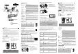
Product Profile & Outline
POWER
ERR
RUN
DR 2
DR 1
IN 0
DR 0
X
16
X
16
2
3
5
4
6
7
8
9
1
GN D
SHL D
CAN -
CAN +
40 [1 .5 75 ]
7
[
0
.
2
7
6
]
9
0
[
3
.
5
4
3
]
82 [3 .2 2 8]
Unit: mm/[inch]
1
Extension port
4
POWER indicator
7
CANopen connector
2
Address switch
5
RUN indicator
8
DIN rail
3
Function switch
6
ERR indicator
9
DIN rail clip
ENGLISH
Specifications
CANopen Connector
Type Removable connector (5.08mm)
Transmission method CAN
Transmission cable 2 communication cables, 1 grounding cable, 1 shielded cable
Electrical isolation 500V DC
Communication
Message type PDO, SDO, SYNC (synchronous object), Emergency (emergency object), NMT
Series transmission
speed
10k, 20k, 50k, 125k, 250k, 500k, 800k, 1M bps (bits per second)
Product code 83
Equipment type 0
Company ID 477 (Delta Electronics, Inc.)
Electrical Specifications
Weight (approx. g) 130 (g)
Current 28mA (typical); impulse current 125mA (24V DC)
Voltage Supplied by DVP-EH2 MPU
Environment
Standards IEC 61131-2, UL508
Noise immunity
RS (IEC 61131-2, IEC 61000-4-3): 80MHz ~ 1,000MHz, 1.4GHz ~ 2GHz, 10V/m
EFT (IEC 61131-2, IEC 61000-4-4): Analog & Communication I/O: 1KV
ESD (IEC 61131-2, IEC 61000-4-2): 8KV Air Discharge
Storage/operation
Operation: 0°C ~ 55°C (temperature); 50 ~ 95% (humidity); pollution degree 2
Storage: -25°C ~ 70°C (temperature); 5 ~ 95% (humidity)
Shock/vibration
immunity
International standards: IEC61131-2, IEC 68-2-6 / IEC61131-2 & IEC 68-2-27
Certificates
CE, UL
Components
CANopen Connector
To connect to CANopen network, use the connector enclosed with DVPCP02-H2 or any connectors you can
buy in the store for wiring.
PIN Signal Description
1 GND GND
2 CAN_L Signal-
3 SHIELD Shielded cable
4 CAN_H Signal+
5 - Reserved
4
GN D
SH LD
CA N-
CA N+
5
3
2
1
Address Switch
The two rotary address setup switches set up the node addresses on CANopen
network in hexadecimal form.
Rotary switch x 16
1
x 16
0
Multiple × 16 × 1
N
O
D
E
A
D
D
R
E
S
S
x1 6
0
x1 6
1
Example: If you need to set the node address of DVPCP02-H2 as 26 (1A Hex), simply switch the
corresponding rotary switch of x16
1
to “1" and the corresponding rotary switch of x16
0
to”A”.
Switch setting Description
0x01
~
0x7F Valid CANopen node address
0, 0x80
~ 0xFF Invalid CANopen node address
Note: The changed values on switches are only
valid when DVPCP02-H2 is re-powered. When
DVPCP02-H2 is operating, changing the set
value of the address will be regarded invalid.
Function Switch (DIP)
DR2 DR1 DR0 Baud rate
OFF OFF OFF 10kbps
OFF OFF ON 20kbps
OFF ON OFF 50kbps
OFF ON ON 125kbps
ON OFF OFF 250kbps
ON OFF ON 500kbps
ON ON OFF 800kbps
ON ON ON 1Mbps
IN0 is reserved.
DR 2
DR 1
IN 0
DR 0
Note: Set up the function switch when the power of DVPCP02-H2 is switched off. Re-power DVPCP02-H2 after the
setup is completed.
Extension Port
The extension port on DVPCP02-H2 is used for the connection to the next DVPCP02-H2 or extension modules
of DVP-EH2 series PLC MPU.
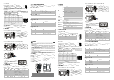
Basic Operation
Connecting DVPCP02-H2 to DVP-EH2 Series PLC MPU
GND
SHLD
CAN-
CAN+
STOP
RUN
0 1
IN
OUT
POWER
RUN
ERROR
BAT.LOW
DVP -20EH
DR 2
DR 1
IN 0
DR 0
Switch off DVP-EH2. Open the connection port on
the right hand side of DVP-EH2 and connect
DVPCP02-H2 to DVP-EH2. Switch on DVP-EH2,
and DVP-EH2 will supply power to DVPCP02-H2.
There is no need to connect DVPCP02-H2 to an
external power supply.
Installing DVP-EH2 and DVPCP02-H2 on DIN Rail
STOP RUN
0 1
IN
OUT
POWER
RUN
ERROR
BAT.LOW
D VP -20 EH
DR 2
DR 1
IN 0
DR 0
GND
SHLD
CAN-
CAN+
1. Use 35mm DIN rail.
2. Open the DIN rail clips on DVP-EH2 and
DVPCP02-H2. Insert DVP-EH2 and
DVPCP02-H2 onto the DIN rail.
3. Clip up the DIN rail clips on DVP-EH2 and
DVPCP02-H2 to fix DVP-EH2 and DVPCP02-H2
on the DIN rail, as shown in the figure.
Connecting to CANopen Connector
G
N
D
S
H
L
D
C
A
N
-
C
A
N
+
Installation & Wiring
1. Install DVPCP02-H2 in an enclosure with sufficient space
around it to allow heat dissipation (see the figure).
2. DO NOT place the I/O signal wires and power supply wire
in the same wiring circuit.
D> 5 0 mm
CP 02-H 2
DD
D
D
EH2 PLC
D
D
Control Register
The control registers (CR) are the registers inside DVPCP02-H2. See the table below for the definitions of all
the CRs. DVP-EH2 series PLC MPU can read or write the CR allowed through DFROM/DTO instructions.
CR# Attribute Content High byte Low byte
#0 Read Model name DVPCP02-H2 model code = H’0240
#1 Read Firmware version
Displaying the current firmware version in hex, e.g. V1.00 is
indicated as H’0100.
#2 Read Length of I/O data Length of output I/O data Length of input I/O data
#3 ~ #102 Read/write
Input data editing area DVPCP02-H2 → data storage area in CANopen master
#103 ~ #202 Read/write
Output data editing area
CANopen master → data storage area in DVPCP02-H2
#203 ~ #215 Set up by the system. DO NOT use it.
#255 Read/write
MPU status
CR#255 = K0: MPU in STOP status
CR#255 = K1: MPU in RUN status
LED Indicators & Trouble-Shooting
There are 3 LED indicators on DVPCP02-H2. POWER indicator displays the status of working power. RUN and
ERR indicators display the working status of DVPCP02-H2 on CANopen network.
Indicator Status & Flash Rate
Indicator status Flash rate
Steady on Constantly on
Blinking
ISO-phase on and off with a frequency of approximately 2,5 Hz: on for approximately
200ms followed by off for approximately 200ms.
Single flash
One short flash (approximately 200ms) followed by a long off phase (approximately
1,000ms).
Double flash
A sequence of two short flashes (approximately 200ms), separated by an off phase
(approximately 200ms). The sequence is finished by a long off phase (approximately
1,000ms).
POWER LED
LED status Indication How to deal with it?
Off No power
Check the power of DVPCP02-H2 and see if the
connection is normal.
Green light steady
on
Normal
--
RUN LED
LED status Indication How to deal with it?
Off No power
Check the power of DVPCP02-H2 and see if the
connection is normal.
Green light single
flash
DVPCP02-H2 in STOP status --
Green light blinking
DVPCP02-H2 in
pre-operational status
--
Green light steady on
DVPCP02-H2 in operational
status
--
ERR LED
LED status Indication How to deal with it?
Off Normal --
Red light single flash
Bus error exceeds the warning
limit.
Check if the bus connection is correct.
Red light double flash
Error control event Check and make sure the bus connection is normal.
Red light steady on Bus-off
1. Check if the network connection is normal and
re-power it.
2. Send it back to the factory for repair if necessary.
DVPCP02-H2 CANopen CANopen
DVPCP02-H2 DVPCP02-H2 CANopen CANopen
DVP-EH2 PLC
1. CANopen DS301v4.02
2. NMT
3. SDO 1 SDO
4. Run /Error
5. PDO 8 TXPDO RXPDO
PDO
6. LV
POWER
ERR
RUN
DR 2
DR 1
IN 0
DR 0
X
16
X
16
2
3
5
4
6
7
8
9
1
GN D
SHL D
CAN -
CAN +
40 [1 .5 75 ]
7
[
0
.
2
7
6
]
9
0
[
3
.
5
4
3
]
82 [3 .2 2 8]
mm/[inch]
1 4
POWER
7
CANopen
2 5
RUN
8
DIN
3 6
ERR
9
DIN
CANopen
5.08mm
CAN
2 1 1
500V DC
PDO SDO SYNC Emergency NMT
10k 20k 50k 125k 250k 500k 800k 1M bps
83
0
ID 477
( , g)
130 (g)
28mA 125mA (24V DC)
DVP-EH2
IEC 61131-2 UL508
RS (IEC 61131-2, IEC 61000-4-3): 80MHz ~ 1,000MHz, 1.4GHz ~ 2GHz, 10V/m
EFT (IEC 61131-2, IEC 61000-4-4): Analog & Communication I/O: 1KV
ESD (IEC 61131-2, IEC 61000-4-2): 8KV Air Discharge
0°C ~ 55°C 50 ~ 95% 2
-25°C ~ 70°C 5 ~ 95%
IEC61131-2, IEC 68-2-6 / IEC61131-2 & IEC 68-2-27
CE UL
CANopen
CANopen DVPCP02-H2
1 GND GND
2 CAN_L Signal-
3 SHIELD
4 CAN_H Signal+
5 -
4
GN D
SH LD
CA N-
CA N+
5
3
2
1