
Owner Manual


CONNECT TO WATER SUPPLIES.
(HOOK-UPS NOT PROVIDED).
Determine which type of connection you will be
making.
Ball nose risers (3/8" O.D. copper tubing) (1) with
coupling nuts (3) (not supplied) or
1/2" I.P.S faucet connectors (2).
3
1
3
2
CONECTE A LOS SUMINISTROS DE AGUA.
(LAS CONEXIONES NO SON
PROPORCIONADAS).
Determine que tipo de conexión usted va a hacer.
Tubos montantes de nariz redondeada (tubería
de cobre de 3/8" D.E.) (1)con tuercas de
acoplamiento (3) (no proporcionadas), o
conectadores de llave I.P.S. de 1/2" (2).
RACCORDEMENT À LA TUYAUTERIE
D’ALIMENTATION (RACCORDS NON FOURNIS)
Vous pouvez utiliser l’un ou l’autre des modes de
branchement suivants: Tubes-raccords à extrémité
arrondie (tube de cuivre 3/8 po d.e.) (1) avec
écrous de raccordement (3) (non fournis) ou,
raccords 1/2 po IPS pour robinetterie (2) .
D.
3
2
4
1
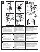
Install Pop-Up Assembly
Instale el Ensamble de Desagüe Automático
Installez le renvoi mécanique
2
Remove stopper (1) and ange (2). Screw
nut (3) all the way down. Push black
gasket (4) down.
Remove pivot nut (1). Install horizontal rod
(2) and stopper (3) as removable (4) or
non-removable (5). Hand tighten pivot nut.
Attach horizontal rod to strap (6) using clip
(7).
A
.
B
.
C
.
D
.
Insert lift rod (1) through faucet and into strap
(2). Tighten screw (3). Connect assembly to
drain (4).
A
.
Quite el tapón (1) y el reborde (2).
Atornille la tuerca (3) completamente
hasta abajo. Empuje el empaque
negro (4) Poussez le joint noir (4)
vers le bas.
C
.
Quite la tuerca del pivote (1). Instale la
barra horizontal (2) y el tapón (3) como
desmontable (4) o fijo (5). Apriete
a mano la tuerca del pivote. Una la
barra horizontal a la barra chata (6)
utilizando el gancho (7).
D
.
B
.
Introduzca la barre de alzar (1) a través de la
llave y dentro en la barra chata (2). Apriete el
tornillo (3). Conecte el ensamble al desagüe (4).
A
.
Enlevez la bonde (1) et la collerette (2).
Vissez l’écrou (3) à fond. Poussez le
joint noir (4) vers le bas.
B
.
Appliquez du composé d’étanchéité à la silicone
sous la collerette (1). Visser le corps (2) sur la
bride et serrer à la main. Alors que le pivot (3) fait
face au robinet, tirez le renvoi directement vers
le bas dans l’orifice de l’évier, puis fixez le joint
(4) et l’écrou (5). NE TOURNEZ PAS LE RENVOI
PENDANT QUE VOUS SERREZ L’ÉCROU EN
LAITON CAR LE COMPOSÉ À LA SILICONE
POURRA NE PAS ASSURER L’ÉTANCHÉITÉ
DU RENVOI. Enlevez l’excès de composé
d’étanchéité.
Enlevez l’écrou de pivot (1). Installez
la tige horizontale (2) et la bonde (3)
pour qu’elle soit amovible (4) ou non
amovible (5). Serrez l’écrou de pivot
à la main. Fixez la tige horizontale au
feuillare (6) à l’aide de l’agrafe (7).
C
.
D
.
Introduisez la tirette (1) dans le robinet et
le feuillard (2). Serrez la vis (3). Raccordez
l’ensemble au renvoi (4).
A. B.
C.
2
1
1
4
3
3
54
3
6
7
2
1
Aplique silicón a la parte interior del reborde
(1). Atornille el cuerpo (2) en la brida y apriete
a mano.
Con el pivote (3) de frente a la llave,
hale el desagüe automático directamente hacia
abajo dentro del drenaje y je el empaque
(4) y la tuerca (5). NO GIRE EL DRENAJE
AUTOMÁTICO MIENTRAS APRIETE LA
TUERCA DE BRONCE O EL SELLADOR
PUEDA NO SELLAR EL DRENAJE.Quite el
exceso de sellador.
Apply silicone to underside of ange (1).
Screw body (2) onto ange and hand tighten.
With pivot (3) facing toward faucet, secure
gasket (4) and nut (5). DO NOT TURN
FLANGE WHILE TIGHTENING NUT OR
SEALANT MAY NOT SEAL DRAIN. Remove
excess sealant.
4
5
2
3
102028 Rev. C