CS24D Color Sensors 130909
Contents 1. Specifications ......................................................................... 6 1.1 Ordering Information* ..........................................................6 2. Introduction........................................................................... 7 2.1 CS24D Features....................................................................8 3. Mounting ............................................................................... 9 4. Interface and Wiring ................
Although great effort has been taken to ensure the accuracy of the information in this document, Delta Computer Systems, Inc. cannot accept responsibility for problems resulting from errors or omissions in this document. The information in this document is subject to change without notice. Neither Delta Computer Systems, Inc.
Figure 1: Sensing Area and Standoff Range for model CS24D-02 5
1. Specifications Model Standoff Distance Standoff Range Sensing Area Response Time Averaging Sorting Modes Sort Criteria Sort Outputs Discrete Inputs Discrete Outputs Indicator LEDs RS232 Serial Ratio Variation with Sensing Distance Stability Supply Voltage Supply Current Enclosure Environment CS24D-00 CS24D-01 CS24D-02 CS24D-03 0.75 to 0.88” (20-22mm) optimum 1.75 to 2.00” (45-50mm) optimum 0.63 to 1.00” (16-25mm) 1.50 to 2.25” (38-57mm) 0.28 x 0.32 @ 0.75” 0.15 x 0.17 @ 0.75” 0.47 x 0.54 @ 1.75” 0.
2. Introduction The CS24D color sensor can sort up to fifteen different colors by comparing against Teach values.
The discrete inputs and outputs are compatible with 12-24 Volt systems and are polarity independent for compatibility with virtually any PLC. Inputs and outputs are not individually isolated but have separate common pins and are fully isolated from the power input as well as the CS24D internal circuitry and RS232 port. The power input accepts 12-24Vdc and is isolated from other pins.
3. Mounting The CS24D-00 and -01 should be mounted such that the bottom is 0.75 to 0.88 inches from the average target object position (standoff distance). This will allow for sensor to object variation of ±1/8 inch. The longer standoff CS24D-02 and -03 should be mounted such that the bottom is 1.75 to 2.00 inches from the average target object position for a standoff tolerance of ±1/4. (See Specifications for standoff and range for other models). An additional 3.
4. Interface and Wiring The CS24D discrete inputs and outputs are compatible with 12-24 Volt systems and are polarity independent for compatibility with virtually any PLC. Four (4) discrete outputs convey the sensing results. These results are binary coded which allows for sixteen conditions—fifteen Sort Outputs plus a No Match output (all outputs off). These solid state relay (SSR) outputs are optically isolated from all other circuitry.
4.1 Discrete I/O Specifications CS24D Discrete I/O Specifications Inputs Four (one group with common) Input type 12-24VDC; sinking (sourcing drive) Input Isolation 500VAC RMS optically isolated (see Section 4.3) (Teach and Hold) 7 to 29Vdc (polarity independent), 3mA maximu m Input “High” range (Mode and Select) 8 to 29Vdc (polarity independent), 3mA maximu m (Teach and Hold) 0 to 3.5VDC (polarity independent), <1mA Input “Low” range (Mode and Select) 0 to 2VDC (polarity independent), <0.1mA (Hold) 1.
4.4 Wiring and Cable Details The CS24D has two connectors: one containing the Teach inputs and ColorSense serial port and the other handling the outputs and power input. The connectors are environmental din-style. The standard cables for the CS24D are ten feet long with straight connectors and pigtails. Other cable options are available—see ordering information. Figure 6: CS24D connector pin designations (wire colors are for standard cables).
Figure 7: CS24D standard cables. (Order CS24D-xx Kit to include with sensor).
5. Teaching The CS24D has the unique capability of being taught with eight samples for each Sort Output (each color to be recognized). The mean and standard deviation (SD) are used to improve sorting performance. Caution: It is very important to teach each Sort Output using eight different samples that represent the normal distribution of colors for the given Sort Output. The orientation of the objects to the sensor must be exactly as during actual operation—include normal variations.
sensing area. 5.3 Teaching using Discrete Inputs The CS24D discrete inputs can be exercised via PLC outputs or mechanical switches. They are compatible with 12-24V DC signals and are accessed via the 8-pin connector. See Interface and Wiring section for details. To Teach the CS24D using discrete inputs, set up the sensor in its normal operating position and conditions, and follow this procedure for each sample color: 1. Select Teach mode by activating the Mode input.
5.4 General Teach Information Once an output is taught, the mean and SD for the Sort Output are immediately stored in the color sensor (overwriting any previous data) and the individual data from the eight readings is deleted. When the sensor is in Teach mode, the outputs are held OFF (No Match condition when in Run mode). In Teach mode, the Output LEDs show the output being taught, not the actual output state.
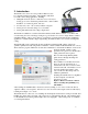
5.5 Saving Teach Data Using the Sort Editor screen in the ColorSense program, Teach data can be uploaded from the sensor, downloaded to sensor, read from a file, and saved to a file. (The Teach data can also be modified using this screen; however, this is for advanced applications and care must be taken to prevent degradation of the sensor performance). To access this function, select the Sort Editor screen from the Tools menu.
6. ColorSense Program Main Screen The main ColorSense screen has a large window for all of the sub-screens and a menu bar across the top. To get started, connect between the CS24D color sensor’s serial port and the PC serial port (or USB port through an adapter), and click on the Connect (auto) button. The program will automatically find the correct port and establish the connection. Once connected the button will change to read Disconnect (COMn) and the Current Reading screen will appear.
7. Setting Options using the Setup Wizard For many applications, the CS24D sensor will perform adequately using default settings. However, with the Setup Wizard in Delta’s ColorSense program, it is easy to enhance performance by tailoring the parameters to the needs of your application. From the ColorSense program, select Setup Wizard from the Tools menu.
Error Limit: This parameter allows you to specify a maximum permissible error for a color to be considered a match. The default value is 5,000. See Optimizing for more information. Closest Color mode can be the best mode for some sorting applications, but is rarely useful for the common color verification applications. Closest Match mode provides more intuitive operation for the majority of applications. Unique Match mode provides more flexibility in flagging colors that may be out of the normal range. 7.
7.4 CS24D Options Summary In addition to the Setup Wizard, options can also be viewed and changed using the Sensor Options screen under the Settings menu. Once parameters are set, they can be downloaded to the sensor by pressing on the OK or Apply buttons (OK also exits the screen). Pressing Cancel will exit with changing sensor settings. The chart below shows the configuration parameters for the CS24D.
8. Optimizing Performance The CS24D analyzes four values: red, green, blue, and intensity. The intensity value is used directly, and the blue, red, and green readings are divided by the intensity value to form ratios. The Blue, Red, and Green ratios contain the color information, while the Intensity contains the hue information. The CS24D has a unique intensity measurement that gives it a stronger and more stable signal for better performance on dark colors without the need to adjust the LED intensity.
With some sorting modes, a second criterion is used to further refine the performance. A limit to the maximum Error, called the Error Limit, can be used to ensure that the colors match to within a set tolerance. The CS24D has the following Sorting Mode choices: Closest Color: One sort output would always be turned ON as the best-fit. Does not use the Error Limit parameter or the No Match output (all outputs off).
8.3 Optimizing using the Analyze screen The Analyze screen shows the predicted performance for the Teach data, which is shown as the number of standard deviations separating each Sort Output. Values less than 3 indicate that the sensor has a hard time differentiating between the target colors, and values greater than 5 indicate a high degree of confidence. (The range of the numbers is from 0.0 to 100.
8.4 Graph and Sort Error Tools The Graph screen shows each color in the Teach data drawn together on a graph. This helps to visualize difficult points where taught colors overlap due to similarity or a large standard deviation. The graph shows the sort data separated out by red, green, blue and intensity. A Sort Output taught to a color with a large standard deviation will display as a wide curve, darker colors will display to the left of the graph, and lighter colors will display on the right.
8.5 Averaging and Response Time Since the internal signals used by CS24D can be fairly weak (especially with dark target colors), they are subject to a variety of electrical and optical noise sources. The CS24D uses an exponential moving averaging allowing up to 4096 readings to be averaged to reduce noise. In many applications, averaging provides significant performance improvements, and we generally recommend setting the averaging as high as is practical. The limiting factor is the response time.
9. Characteristics 9.1 Temperature The feedback circuitry automatically compensates for the normal LED intensity variation with temperature yielding a typical stability of 0.05%/C. In the most critical applications, the CS24D should be maintained at a constant temperature since the LED color varies slightly with temperature. 9.2 Edge Effects The CS24D series have large sensing areas. (The CS24D-02, for example, sees an area of approximately 0.5 inches square).
9.6 General Information The term "color" actually implies visible light--wavelengths from about 400nm (violet) to about 750nm (deep red), although in this document any wavelength that can be seen by the CS24D is referred to as a color. With high intensity blue LEDs (450nm) and several visible wavelengths up to 700nm available, Delta’s sensors can be made to see practically the entire visible color spectrum.
11. Frequently Asked Questions Q. How many different target colors can the CS24D sort? A. The CS24D can be programmed to differentiate up to fifteen (15) colors simultaneously. Its four discrete outputs are binary-coded to indicate no match (all off) or 1 to 15 outputs. Q. What if my materials are textured? A. The CS24D successfully handles a variety of textured, grained, and other difficult surfaces where other color sensors give inconsistent readings. Q. Can the CS24D work with patterned materials? A.
is needed and for maximum consistency, bright ambient light (such as sunlight) should be blocked from the sensing area. Q. What are the power requirements for the CS24D? A. The CS24D is rated for 12-24Vdc ±20% and 50mA maximum. Typical current draw is about 30mA. The power supply must be able to provide a startup surge current of about 250mA. Although the power supply is not critical, for best noise performance a dedicated, linear supply is recommended. The power input is fully isolated. Q.
closest to the sensor is 3/4 by 2 1/2 inches and tapers down to about 1/2 x 1 inches. (Figures 1 and 3 show the critical sensing and light areas). Q. Can I use the CS24D pointing up? A. The CS24D can be mounted in any orientation. With the sensor pointing up, it is important to watch dust build-up on the sensing window. Also sunlight should not be allowed to enter directly into the sensor window. Q. How often should the CS24D be re-taught? A.
Time: There is a certain amount of reading variation over time, typically a few tenths of a percent per week or less. This effect is compensated for in the CS24D. 12. Troubleshooting The CS24D's indicator LEDs provide helpful troubleshooting information. The output LEDs use binary coding to indicate which channel is active. (In Teach mode, the Output LEDs show the output being taught, not the actual output state).
15. Warranty Hardware products will conform to Delta’s material specifications and be free of defects in material and workmanship under normal and proper use for a period of one (1) year from date of shipment to Customer by Delta or its authorized distributor. Repaired or replacement products are similarly warranted for six (6) months or the remainder of the original warranty term, whichever is longer.
Index Angle, 25 Applications, 26 Calibration, 15 Re-, 29 Cleaning, 26 LEDs, 7, 15, 25, 26, 30 Aging, 15 Operating life, 15 Mounting, 8 Orientation, 29 Power supply, 10 Ratios, 25 Standoff distance, 5, 27 Target object, 8, 25 Temperature, 7, 25 Wiring, 9 34