
Service manual


24
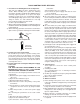
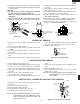
MAGNETRON REMOVAL
Removal
1. Disconnect the power supply cord and then remove
outer case.
2. Remove the oven cavity assembly from the base plate.
Refer to "OVEN CAVITY ASSEMBLY REMOVAL".
3. Discharge the high voltage capacitor.
4. Now, the wire leads should be disconnected from the
magnetron and thermal cut-out (MG).
5. Carefully remove the four (4) screws holding magnetron
to waveguide flange.
6. Remove magnetron with care so that magnetron antenna
is not hit by any metal object around antenna.
7. Remove the one (1) screw holding the magnetron duct
assembly to the magnetron.
8. Remove the magnetron duct assembly with thermal cut-
out (MG) from magnetron.
9. Now, the magnetron is free.
Reinstallation
1. Re-install the magnetron thermal duct assembly with
thermal cut-out (MG) to magnetron with the one (1)
screw.
2. Re-install the magnetron to waveguide flange with the
four (4) screws.
3. Re-install the oven cavity assembly to the base plate.
Refer to "OVEN CAVITY ASSEMBLY REMOVAL".
4. Reconnect the wire leads to the magnetron and thermal
cut-out (MG). Refer to "PICTORIAL DIAGRAM" on page
29.
5. Re-install outer case and check that the oven is operating
properly.
CAUTION: WHEN REPLACING MAGNETRON, BE SURE
THE R.F. GASKET IS IN PLACE AND MOUNT-
ING SCREWS ARE TIGHTENED SECURELY.
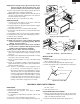
OVEN LAMP REMOVAL
1. Disconnect the power supply cord and remove outer
case.
2. Open the door and block it open.
3. To discharge the high voltage capacitor, wait for 60
seconds.
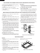
transformer from the high voltage capacitor.
6. Remove one (1) screw holding capacitor holder to base
plate.
7. Remove one (1) screw holding high voltage rectifier
assembly to capacitor holder.
8. Disconnect rectifier terminal from the capacitor.
High voltage rectifier assembly is now free.
9. Remove the capacitor holder. The capacitor is now free.
CAUTION: WHEN REPLACING HIGH VOLTAGE RECTI-
FIER AND HIGH VOLTAGE CAPACITOR,
GROUND SIDE TERMINAL OF THE HIGH
VOLTAGE RECTIFIER MUST BE SECURED
FIRMLY WITH A GROUNDING SCREW.
4. Disconnect the wire leads from the oven lamp.
5. Remove the one (1) screw holding the oven lamp to the
lamp angle.
6. Remove the oven lamp from the lamp angle.
7. Now, the oven lamp socket is free.
REMOVAL
1. Disconnect the power supply cord and then remove the
outer case.
2. Remove the oven cavity assembly from the base plate.
Refer to "OVEN CAVITY ASSEMBLY REMOVAL".
3. Discharge the high voltage capacitor.
4. Disconnect the wire leads from the fan motor.
5. Release the main wire harness and the switch harness
from the holes of the fan duct.
6. Remove each one (1) screw holding the separate
angles A, B and C to the base plate. And remove them
from base plate.
7. Remove two (2) screws holding the fan duct to the base
plate. And remove it from the base plate.
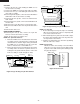
8. Remove the fan blade from the fan motor shaft according
to the following procedure.
9. Hold the edge of the rotor of the fan motor by using a pair
of groove joint pliers.
CAUTION:
* Make sure that no metal pieces enter the gap between
the rotor and the stator of the fan motor because the
rotor is easily shaven by pliers and metal pieces may
be produced.
FAN MOTOR REMOVAL
* Do not touch the pliers to the coil of the fan motor
because the coil may be cut or injured.
* Do not disfigure the bracket by touching with the
pliers.
10.Remove the fan blade from the shaft of the fan motor by
pulling and rotating the fan blade with your hand.
11. Now, the fan blade will be free.
CAUTION:
* Do not reuse the removed fan blade because the
hole (for shaft) may be larger than normal.
12.Remove the two (2) screws holding the fan motor to the
fan duct.
13.Now, the fan motor is free.
14.Another fan motor can be removed in a same way.
INSTALLATION
1. Install the fan motor to the fan duct with the two (2)
screws.
2. Install the fan blade to the fan motor shaft according to
the following procedure.
3. Hold the center of the bracket which supports the shaft
of the fan motor on the flat table.
4. Apply the screw lock tight into the hole (for shaft) of the
fan blade.