
Service manual


28
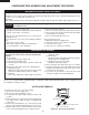
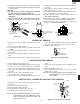
Figure C-9(b). Routing of 7-pin wire harness
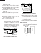
NOTE: For key unit
1. Before attaching a new key unit, wipe off remaining
adhesive on the door frame surfaces completely with
a soft cloth soaked in alcohol.
2. When attaching the key unit to the door frame, adjust
the upper edge and right edge of the key unit to the
correct position of door frame.
3. Stick the key unit firmly to the door frame by rubbing
with soft cloth not to scratch.
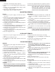
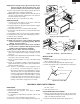
NOTE: For CPU unit
Handle the CPU unit carefully so that the ribbon
cable does not come off. Because the ribbon cable
is glued on the LCD and the printed wiring board
only by heated paste.
Figure C-10. CPU unit
Printed wiring board
of CPU unit
Liquid Crystal
Display (LCD)
Ribbon cable
CPU UNIT
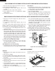
7. Remove the two (2) screws holding the PWB cover to
the door frame assembly.
8. Remove the PWB cover from the door frame assembly.
9. Remove the one (1) screw holding the CPU unit to the
door frame assembly.
10.Releasing the two (2) tabs, remove the CPU unit with the
LCD holder from the door frame assembly.
11.Releasing the two (2) tabs, release the LCD from the
LCD holder.
12.Releasing the four (4) tabs, remove the LCD holder from
the CPU unit.
13.Disconnect the 7-pin wire harness from the CPU unit.
14.Disconnect the ribbon cable of the key unit from the CPU
unit.
15.Now the CPU unit is free.
DOOR FRAME ASSEMBLY
16.Releasing the four (4) tabs, remove the 7-pin wire
harness from the door frame assembly.
19.Now, the door frame assembly is free.
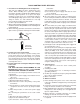
NOTE: For 7-pin wire harness
1. Before the PWB cover is reinstalled to the door frame
assembly, route the 7-pin wire harness under the tab
of LCD holder as shown in Figure C-9(a). And when
the PWB cover is reinstalled, route the 7-pin wire
harness under the hole of the PWB cover.
2. Before the door panel is reinstalled to the door frame
assembly, make sure that the 7-pin wire harness is
held by the four (4) tabs and two (2) holes on the door
frame assembly as shown in Figure C-10(b).
PWB Cover
CPU unit
Door frame Hole of
PWB cover
Tab of LCD holder
7-pin wire harness
PWB Cover
Tab
Tab
Tab
Hole on door frame
Hole on door frame
Hole of PWB cover
Door frame
Tab
7-pin wire harness
Figure C-9(a). Routing of 7-pin wire harness