
User's Manual

Chapter 3 Creating and Editing Screens
Revision May, 2010 3-145
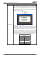
3.8.9 Graph Display Elements
Fig. 3-8-26 Graph Display Elements
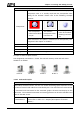
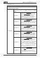
3.8.9.1 State Graphic
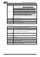
Property Description of Static Graphic Element
When HMI is connected to the controller, the user can create static graphic elements to
read the value of several read addresses controlled by the controller. The read value of
each state can be converted and transmitted to the static graphic elements and display
respectively on the HMI screen.
Read Address
The address can be internal memory or the controller address.
(Please refer to Table 3-8-2 Property Description of General
Buttons.)
Bank (Picture Bank)
Picture Name
(Please refer to Table 3-8-2 Property Description of General
Buttons.)
Transparent Effect
Transparent Color
(Please refer to Table 3-8-2 Property Description of General
Buttons.)
Foreground Color (Please refer to Table 3.2.2 Property Description of Numeric
Display Elements.)
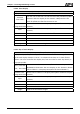
Bit It can have two states.
Word It can have 256 states.
Data Length
LSB It can have 16 states.
Data Format
It provides BCD, Signed Decimal, Unsigned Decimal and Hex four
kinds of data format to define the read memory content.
Add/Remove State
It is used to set the state numbers of static graphic element. If the
data length of the value is in Word, 1~256 states can be set. If the
data length of the value is in LSB, 16 states can be set. If the data
length of the value is in Bit, only 2 states can be set.