
User's Manual

Chapter 3 Creating and Editing Screens
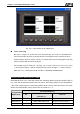
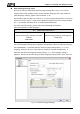
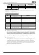
Fig. 3-4-5 Curve Elements on HMI Screen
Curve Clear Flag
Bits 8 to 11 (flags 1 to 4) clear the curve (Trend Graph, X-Y Chart, X-Y distribution or
Curve Input) when this flag is turned ON (For more details on the settings of curve
element, please refer to section 3.8.10). To control the curve clear flag again, this flag
must be turned OFF and then ON again.
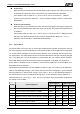
For example (refer to Table 3-4-1 and Fig. 3-4-5), if D2 is set to 512 or $17.9 is set to
1, the curves of figure 3 will be cleared and the curves of figure 1, 2 and 4 will not.
When D2=512, it indicates that Bit 9 of D2 is 1(0000 0010 0000 0000).
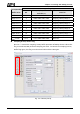
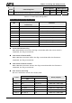
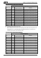
Sampling History Buffer Register (HBSR)
Delta DOP-B series has 12 Bits that control the sampling address of history buffer (refer to
Fig. 3-4-6 and the following table). Not only Timer, the history buffer can be controlled by
a PLC if the Trigger Source in the History Buffer setup is set to a PLC from Timer. For more
details on History Buffer setup, please refer to section 3.11.3.
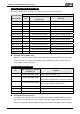
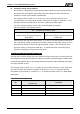
Corresponding Flag
Corresponding
Buffer Area
Bit
Binary Display of Relative
Position (x)
Function
Buffer Area 1 0 0000 0000 0000 000x Sampling History Buffer 1
Buffer Area 2 1 0000 0000 0000 00x0 Sampling History Buffer 2
Buffer Area 3 2 0000 0000 0000 0x00 Sampling History Buffer 3
3-30 Revision May, 2010