Note: Rockler may not carry all products and/or sizes listed in this vendor's publication (Model DP300L) 21450 RTD10000255AA PART NO. A14210-10-27-05 Rev. B Copyright © 2005 Delta Machinery To learn more about DELTA MACHINERY visit our website at: www.deltamachinery.com. For Parts, Service, Warranty or other Assistance, please call ESPAÑOL: PÁGINA 21 FRANÇAISE : PAGE 41 1-800-223-7278 (In Canada call 1-800-463-3582).
TABLE OF CONTENTS IMPORTANT SAFETY INSTRUCTIONS . . . . . . . . . . . . . . . . . . . . . . . . . . . . . . . . . . . . . . . . . . . . . . . . . . . . . . . . . . . 2 SAFETY GUIDELINES - DEFINITIONS . . . . . . . . . . . . . . . . . . . . . . . . . . . . . . . . . . . . . . . . . . . . . . . . . . . . . . . . . . . 3 TOOL WARNING LABEL . . . . . . . . . . . . . . . . . . . . . . . . . . . . . . . . . . . . . . . . . . . . . . . . . . . . . . . . . . . . . . . . . . . . . . 3 GENERAL SAFETY RULES . . . . .
SAFETY GUIDELINES - DEFINITIONS It is important for you to read and understand this manual. The information it contains relates to protecting YOUR SAFETY and PREVENTING PROBLEMS. The symbols below are used to help you recognize this information. Indicates an imminently hazardous situation which, if not avoided, will result in death or serious injury. Indicates a potentially hazardous situation which, if not avoided, could result in death or serious injury.
GENERAL SAFETY RULES READ AND UNDERSTAND ALL WARNINGS AND OPERATING INSTRUCTIONS BEFORE USING THIS EQUIPMENT. Failure to follow all instructions listed below, may result in electric shock, fire, and/or serious personal injury or property damage. IMPORTANT SAFETY INSTRUCTIONS 1. 2. 3. 4. 5. 6. 7. 8. 9. 10. 11. 12. 13. 14. FOR YOUR OWN SAFETY, READ THE INSTRUCTION MANUAL BEFORE OPERATING THE MACHINE.
ADDITIONAL SPECIFIC SAFETY RULES FAILURE TO FOLLOW THESE RULES MAY RESULT IN SERIOUS INJURY. 1. 2. 3. 4. 5. 6. 7. 8. 9. 10. 11. 12. 13. DO NOT OPERATE THIS MACHINE until it is completely assembled and installed according to the instructions. A machine incorrectly assembled can cause serious injury. OBTAIN ADVICE from your supervisor, instructor, or another qualified person if you are not thoroughly familiar with the operation of this machine. Knowledge is safety.
ADDITIONAL SAFETY RULES FOR THE LASER FAILURE TO FOLLOW THESE RULES MAY RESULT IN SERIOUS INJURY. EYE INJURY -LASER LIGHT * * Do not stare into beam aperture, or into a reflection from a mirror-like surface Do not use optical tools such as a telescope or transit to view the laser beam * * * * EYE INJURY - LASER LIGHT Do not operate the laser around children or allow children to operate the laser.
POWER CONNECTIONS A separate electrical circuit should be used for your machines. This circuit should not be less than #12 wire and should be protected with a 20 Amp time lag fuse. If an extension cord is used, use only 3-wire extension cords which have 3-prong grounding type plugs and matching receptacle which will accept the machine’s plug.
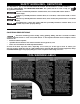
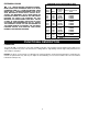
EXTENSION CORDS MINIMUM GAUGE EXTENSION CORD RECOMMENDED SIZES FOR USE WITH STATIONARY ELECTRIC MACHINES USE PROPER EXTENSION CORDS. MAKE SURE YOUR EXTENSION CORD IS IN GOOD CONDITION AND IS A 3-WIRE EXTENSION CORD WHICH HAS A 3-PRONG GROUNDING TYPE PLUG AND MATCHING RECEPTACLE WHICH WILL ACCEPT THE MACHINE’S PLUG. WHEN USING AN EXTENSION CORD, BE SURE TO USE ONE HEAVY ENOUGH TO CARRY THE CURRENT OF THE MACHINE.
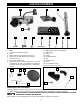
CARTON CONTENTS 2 1 13 12 1. 2. 3. 4. 5. 6. 7. 8. 9. 3 4 11 10 9 Drill Press Head and Motor Table Column, Base Flange and Rack Base M8x1.25x25mm Hex Head Cap Screws (4) Worm Gear for Table Raising and Lowering Hex Wrenches (2) Pinion Shaft Handles (3) M8x1.25x125mm Carriage Head Screws (2), M8 Flat Washers (2), M8.1 Lock Washers (2), M8x1.25 Hex Nuts (2) (for fastening the base to a supporting surface) 8 7 6 5 10. Chuck Key 11. Table Raising and Lowering Handle 12. Table Clamp 13. Chuck 14.
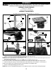
ASSEMBLY For your own safety, do not connect the machine to the power source until the machine is completely assembled and you read and understand the entire instruction manual. ASSEMBLY TOOLS REQUIRED Hex Wrenches - (supplied) 1/2 open end wrench - (not supplied) ASSEMBLY TIME ESTIMATE Assembly for this machine takes approximately 15 to 30 minutes. H G D E F A B C Fig. 3 Fig. 4 J F I G G Fig. 5 Fig. 6 K F J L F Fig. 7 Fig. 8 1. Attach the column (A) Fig.
6. Insert the clamp (B) Fig. 10 through the mounting bracket, under the raising rack, and around the column. Tighten the hose clamp securely. Assemble the mounting arm (C) into the bracket hole (D) Fig. 10 and attach tray (T) to the mounting arm. Be sure the bracket, mounting arm and raising rack are positioned in relation to the drill press table as shown in Fig. 9. Install the ring (E) Fig. 11 (removed in STEP 1) on the column. 7. 8. 9.
EYE INJURY - LASER LIGHT. DO NOT STARE INTO THE LASER BEAM OR APERTURE OR INTO A REFLECTION FROM A MIRROR-LIKE SURFACE. 12. Screw front laser housing (A) Fig. 14 to the rear laser housing (B) loosely using the two socket head cap screws (C) Fig. 14A inset included in laser packaging. B A 13. Place this laser housing assembly onto the drill press column (D) Fig. 14A and rest it on the collar (E) Fig. 14A. Fig. 14 14. Tighten the screws (C) Fig.
18. Seat the drill press head (N) Fig. 15 on the column (U). Align the head (A) Fig. 15A, with the table (B) and base (C). Tighten the two head locking screws (O) Fig. 15 with the supplied wrench. 19. Thread the three pinion shaft handles (P) Fig. 16 in the three tapped holes located in the pinion shaft (S). O N NOTE: Make certain that the spindle taper (Q) Fig. 17 and the tapered hole in the chuck (R) are clean and free of grease, lacquer, or rust preventive coatings.
OPERATION OPERATIONAL CONTROLS AND ADJUSTMENTS STARTING AND STOPPING THE DRILL PRESS 1. The on/off switch (A) Fig. 20 is located on the front of the drill press head. To turn the machine "ON", move the switch up to the "ON" position. 2. To turn the machine "OFF", move the switch (A) down to the "OFF" position. Make sure that the switch is in the "OFF" position before plugging in the power cord. In the event of a power failure, move the switch to the "OFF" position. An accidental start-up can cause injury.
TABLE ADJUSTMENTS 1. Raise or lower the table on the column by loosening the table clamp (A) Fig. 23, and turning the table raising and lowering handle (B) Fig. 24. After the table is at the desired height, tighten the clamp (A) Fig. 23. NOTE: Always raise (rather than lower) the table to the final position to allow the gears to mesh and prevent slippage. A Fig. 23 B 2. The table can be rotated 360 degrees on the column by loosening the clamp (A) Fig.
A SPINDLE MOTOR E 3100 2340 1720 1100 C 620 D B Fig. 28 Fig. 29 SPINDLE SPEEDS Five spindle speeds (620, 1100, 1720, 2340, and 3100 RPM) are available with your drill press. See the chart in Fig. 28 to select the correct belt placement for your project. CHANGING SPEEDS AND ADJUSTING BELT TENSION NOTE: A belt-positioning speed chart (E) Fig. 29 is located on the inside top cover of the drill press. Disconnect machine from power source. 1. Open the top cover (A) Fig. 29. 2.
ADJUSTING SPINDLE RETURN SPRING The spindle will automatically return slowly to its upper position when the handle is released. The spindle return spring was properly adjusted at the factory. However, to adjust, if necessary: Disconnect machine from power source. 1. 2. Loosen the nuts (B) and (E) Fig. 31. Make sure that the spring housing (A) remains engaged with head casting (C). While firmly holding the spring housing (A) Fig.
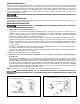
1. Place a piece of wood (K) Fig. L4 on the table and clamp in place. 2. Rotate quill (M) down and make an indention in the wood with the alignment pin (L) Fig. L4. 3. Turn on laser and adjust both beams to cross that point by rotating the laser holder (J) Fig. L5. 4. Check if the lasers line up at different heights by either raising or lowering the table, making a new indention and turning on the lasers to verify they cross at the indention.
INSTALLING AND REMOVING DRILL BITS C B A D Fig. 34 NOTE: Use drill bits with a shank of 1/2" or less in diameter. Disconnect machine from power source. 1. Insert the smooth end of drill bit (A) Fig. 34 in the chuck (B) as far as it will go, and then back the bit out 1/16" (or up to the flutes for small bits). 2. Center the drill bit (A) Fig. 34 in the chuck (B) before tightening the chuck with the key (C). 3. Turn the chuck key (C) Fig.
MAINTENANCE KEEP MACHINE CLEAN LUBRICATION & RUST PROTECTION Periodically blow out all air passages with dry compressed air. All plastic parts should be cleaned with a soft damp cloth. NEVER use solvents to clean plastic parts. They could possibly dissolve or otherwise damage the material. Apply household floor paste wax to the machine table and extension table or other work surface weekly. Or use a commercially available protective product designed for this purpose.
(Modelo DP300L) MANUAL DE INSTRUCCIONES Prensa para Taladro de Banco de 305 mm (12”) (con Guías de Láser) PIEZA NO. A14210 - 10-27-05 Rev. B Copyright © 2005 Delta Machinery Para obtener más información sobre Delta Machinery, visite nuestro sitio web en: www.deltamachinery.com ENGLISH: PAGE 1 FRANÇAISE : PAGE 41 Para las piezas, el servicio, la garantía o la otra ayuda llaman por favor 21 1-800-223-7278 (en 21la llamada 1-800-463-3582 de Canada).
INSTRUCCIONES DE SEGURIDAD IMPORTANTES LEA Y ENTIENDA TODAS ADVERTENCIAS Y LAS INSTRUCCIONES OPERADORAS ANTES DE UTILIZAR CUALQUIER INSTRUMENTO O EL EQUIPO. CUANDO SE USA INSTRUMENTOS O EQUIPO, LAS PRECAUCIONES BÁSICAS DE LA SEGURIDAD SIEMPRE SE DEBEN SEGUIR PARA REDUCIR EL RIESGO DE LA HERIDA PERSONAL. LA OPERACIÓN IMPROPIA, LA CONSERVACIÓN O LA MODIFICACIÓN DE INSTRUMENTOS O EQUIPO PODRÍAN TENER COMO RESULTADO EL DAÑO GRAVE DE LA HERIDA Y LA PROPIEDAD.
NORMAS GENERALES DE SEGURIDAD SI NO SE SIGUEN ESTAS NORMAS, EL RESULTADO PODRÍA SER LESIONES GRAVES. 1. 2. 3. 4. 5. 6. 7. 8. 9. 10. 11. 12. 13. 14. PARA SU PROPIA SEGURIDAD, LEA EL MANUAL DE INSTRUCCIONES ANTES DE UTILIZAR LA MÁQUINA. Al aprender la aplicación, las limitaciones y los peligros específicos de la máquina, se minimizará enormemente la posibilidad de accidentes y lesiones. USE PROTECCIÓN DE LOS OJOS Y DE LA AUDICIÓN. USE SIEMPRE ANTEOJOS DE SEGURIDAD.
NORMAS ESPECÍFICAS ADICIONALES DE SEGURIDAD SI NO SE SIGUEN ESTAS NORMAS, EL RESULTADO PODRÍA SER LESIONES PERSONALES GRAVES. 1. NO OPERE ESTA MÁQUINA HASTA que no esté armada e instalada completamente, según las instrucciones. Una máquina montada de manera incorrecta puede provocar lesiones graves. 2. SOLICITE EL ASESORAMIENTO de su supervisor, instructor o alguna persona calificada si no está familiarizado con el funcionamiento de esta máquina. El conocimiento garantiza la seguridad. 3.
ETIQUETAS AMONESTADORAS DE LA HERRAMIENTA OTRAS REGLAS DE SEGURIDAD PARA EL LÁSER SI NO SE SIGUEN ESTAS NORMAS, EL RESULTADO PODRÍA SER LESIONES PERSONALES GRAVES. LESIONES OCULARES - LUZ LÁSER * No fije la vista en el orificio del rayo ni en su reflejo sobre superficies similares a un espejo. * No utilice herramientas ópticas, como por ejemplo un telescopio o un teodolito para ver el rayo láser. LESIONES OCULARES - LUZ LÁSER * No opere el láser con niños alrededor ni permita que los niños operen el láser.
CONEXIONES A LA FUENTE DE ALIMENTACIÓN Debe utilizarse un circuito eléctrico independiente para las máquinas. Este circuito debe tener alambre de no menos del No. 12 y debe estar protegido con un fusible de acción retardada de 20 A. Si se utiliza un cordón de extensión, utilice únicamente cordones de extensión de tres alambres que tengan enchufes de tipo de conexión a tierra con tres terminales y un receptáculo coincidente que acepte el enchufe de la máquina.
CORDONES DE EXTENSIÓN CORDONES DE EXTENSIÓN CORDÓN DE EXTENSIÓN DE CALIBRE MÍNIMO TAMAÑOS RECOMENDADOS PARA USO CON MÁQUINAS ELÉCTRICAS ESTACIONARIAS UTILICE CORDONES DE EXTENSIÓN APROPIADOS. ASEGÚRESE DE QUE EL CORDÓN DE EXTENSIÓN ESTÉ EN BUENAS CONDICIONES Y DE QUE SEA UN CORDÓN DE EXTENSIÓN DE TRES ALAMBRES QUE TENGA UN ENCHUFE DE TIPO DE CONEXIÓN A TIERRA CON TRES TERMINALES Y UN RECEPTÁCULO COINCIDENTE QUE ACEPTE EL ENCHUFE DE LA MÁQUINA.
CONTENIDO DE CARTON 2 1 13 12 3 4 11 10 9 8 7 6 5 Fig. 1 1. 2. 3. 4. 5. 6. 7. 8. Cabezal y motor de la taladradora Mesa Columna, pestaña de base, y mecanismo de elevación de mesa Base Tornillos de tapón de cabeza hexagonal de M8x1.25x25mm (4) Tornillo sin fin para el mecanismo de elevación y bajado de mesa Llaves (2) Agarraderas del eje del piñón (3) 14 15 16 9. 10. 11. 12. 13. 14. 15. 16. 17. 18. 19. 20. Tornillos de Carrocería de M8x1.25x125 mm (2), M8 arandelas planas (2), M8.
ENSAMBLAJE HERRAMIENTAS DE ENSAMBLAJE REQUERIDAS Llaves hexagonales (suministradas) Llave abierta 1/2 (no suministrada) ESTIMACIÓN DEL TIEMPO DE ENSAMBLAJE La asamblea para esta máquina es más o menos 1-2 horas. PARA SU PROPIA SEGURIDAD, NO CONECTE LA MAQUINA A LA FUENTE DE ENERGIA HASTA QUE LA MAQUINA HAYA SIDO ENSAMBLADA POR COMPLETO Y USTED HAYA LEIDO Y ENTENDIDO COMPLETAMENTE EL MANUAL DEL PROPIETARIO. H G D E F A B C Fig. 3 Fig. 4 J F I G G Fig. 5 J Fig. 6 K F L F Fig. 7 1. Fig.
6. Inserte la abrazadera (B), Fig. 10, a través del soporte de montaje debajo de la cremallera de elevación y alrededor de la columna. Ajuste la abrazadera de la manguera son firmeza. 7. Ensamble el brazo de montaje (C) en el orificio del soporte (D), Fig. 10, y adjunte la bandeja (T) al brazo de montaje. 8. Asegúrese de que el soporte, el brazo de montaje y la cremallera de elevación estén colocados en relación con la mesa de la prensa de taladro como se muestra en la Fig. 9. 9. Instale el anillo (E), Fig.
ENSAMBLADO DEL LÁSER Lesiones oculares - Luz láser. No fije la vista en el rayo del láser o en el orificio, ni en un reflejo sobre superficies similares a un espejo. B 12. Atornille la parte frontal de la caja del láser (A), Fig. 14, a la parte posterior de la caja del láser (B) sin ajustar excesivamente con los dos tornillos de cabeza troncocónica para enchufes (C) Fig. 14A inserción incluidos en el embalaje del láser. A 13.
18. Coloque la cabeza de la prensa de taladro (N), Fig. 15, en la columna (U). Alinee la cabeza (A), Fig. 15A, con la mesa (B) y la base (C). Ajuste los dos tornillos de bloqueo de la cabeza (O), Fig. 15, con la llave suministrada. 19. Enrosque los tres mangos del eje del piñón (P), Fig. 16, en los tres orificios roscados ubicados en el eje del piñón (S). NOTA: Asegúrese de que el cono del eje (Q), Fig.
OPERACIÓN CONTROLES Y AJUSTES OPERACIONALES ARRANCANDO Y DETENIENDO LA PRENSA PARA TALADRO DE BANCO El interruptor de ENCENDIDO/APAGADO (A) Fig. 20 está localizadoen la parte delantera del cabezal de la taladradora. Para ENCENDER la máquina, mueva el interruptor (A) a la posición elevada. Para APAGAR la máquina, mueva el interruptor (A) a la posición inferior. CERCIÓRESE QUE EL INTERRUPTOR ESTÁ EN EL “LEJOS” LA POSICIÓN ANTES DE CONECTAR LA CUERDA DEL PODER.
B D C Fig. 24 E Fig. 25 C D E F Fig. 26 3. 4. 5. Fig. 27 La mesa puede inclinarse a la derecha o a la izquierda al extraer y quitar el pasador de alineamiento de la mesa (C) Fig. 25 y al aflojar el perno de cierre de la mesa (D). NOTA: Si se hace difícil la extracción del pasador (C), vire la tuerca (E) contra el sentido de las manecillas del reloj para extraer el pasador de la estructura. Incline la mesa al ángulo deseado y apriete el perno (D).
1. 2. Levante la correa y el protector de polea (A) Fig. 29. Suelte la tensión de la correa aflojando la perilla de cierre de tensión (B) Fig. 29, articulando el motor hacia la parte delantera de la taladradora. 3. Sostenga el motor en esta posición y coloque la correa (c) en usted seleccionó velocidades según la carta en Fig. 28. 4. Mueva el motor a la parte posterior hasta que la correa tiene tensión apropiada.
AJUSTE DEL LÁSER Desconecte la máquina de la fuente de energía. Luz láser. No fije la vista en el rayo, en el orificio o en un reflejo sobre superficies similares a un espejo. CÓMO COLOCAR LOS LÁSERES EN PARALELO 1. Instale la clavija de alineación (A) en el portabrocas (B). Asegúrese de que el extremo de punta (C) de la clavija de alineación esté hacia abajo, como se muestra en la Fig. L1. La línea negra trazada debe estar frente al láser izquierdo como se muestra. 2.
UTILIZAR LA MAQUINA El uso de accesorios y conexiones no recomendadas por DELTA puede resultar en el riesgo de lesionamiento. IMPORTANTE: Cuando el material Fig. 33 es lo suficientemente largo, debe ser colocado siempre sobre la B mesa con un extremo contra la columna (B) para evitar que el objeto rote. Si no resulta posible apoyar el material de trabajo contra la columna, deben utilizarse abrazaderas o un tornillo de banco para sujetar el material contra la mesa.
PERFORACION DE MADERAS Las brocas espirales, aunque estén diseñadas para la perforación de metales, pueden ser utilizadas también para el taladrado de agujeros en la madera. No obstante, se prefiere por lo general el uso de brocas de espuela maquinadas para la perforación de madera, ya que cortan un agujero de fondo cuadrado y están diseñadas para la extracción de astillas de madera.
LOCALIZACION DE FALLAS Para obtener asistencia para su máquina, visite nuestro sitio Web en www.deltamachinery.com para tener acceso a una lista de centros de servicio o llame a la línea de ayuda de Delta Machinery al 1-800-223-7278. (En Canadá, llame al 1-800-463-3582.) MANTENIMIENTO MANTENGA LA MÁQUINA LIMPIA Periódicamente sople por todas las entradas de aire con aire comprimido seco. Todas las piezas de plástico deben limpiarse con un paño suave y húmedo.
GARANTIA Para registrar la herramienta para obtener el mantenimiento cubierto por la garantía de la herramienta, visite nuestro sitio web en www.deltamachinery.com.
(Modèle DP300L) No. de pièce A14210 - 10-27-05 Rev. B Copyright © 2005 Delta Machinery Pour apprendre plus de la MACHINERIE DE DELTA visite notre site web à: www.deltamachinery.com. Pour les Parties, le Service, la Garantie ou l'autre Assistance, ENGLISH: PAGE 1 ESPAÑOL: PÁGINA 21 s'il vous plaît appeler 1-800-223-7278 (Dans l'appel de Canada 1-800-463-3582).
LES INSTRUCTIONS IMPORTANTES DE SURETE LIRE ET COMPRENDRE TOUTES INSTRUCTIONS D'AVERTISSEMENTS ET OPÉRATION AVANT D'UTILISER N'IMPORTE QUEL OUTIL OU N'IMPORTE QUEL ÉQUIPEMENT. EN UTILISANT LES OUTILS OU L'ÉQUIPEMENT, LES PRÉCAUTIONS DE SÛRETÉ FONDAMENTALES TOUJOURS DEVRAIENT ÊTRE SUIVIES POUR RÉDUIRE LE RISQUE DE BLESSURE PERSONNELLE. L'OPÉRATION DÉPLACÉE, L'ENTRETIEN OU LA MODIFICATION D'OUTILS OU D'ÉQUIPEMENT ONT POUR RÉSULTAT LA BLESSURE SÉRIEUX ET LES DOMMAGES DE PROPRIÉTÉ.
RÈGLES DE SÉCURITÉ GÉNÉRALES Lisez le Guide de l’utilisateur. Ne tentez pas d’utiliser cet appareil avant d’avoir lu les directives sur la sécurité, l’assemblage, l’utilisation et l’entretien de ce Guide de l’utilisateur. L’INOBSERVATION DE CES RÈGLES PEUT CONDUIRE À DES BLESSURES GRAVES. 1.
RÈGLES SPÉCIFIQUES ADDITIONNELLES DE SÛRETÉ RISQUE D’OPÉRATION PEU SÛRE. L’inobservation de ces règles peut conduire à des blessures graves. 1. NE PAS FAIRE FONCTIONNER CETTE MACHINE AVANT QU’ELLE NE SOIT ENTIÈREMENT ASSEMBLÉE ET INSTALLÉE CONFORMÉMENT À CES DIRECTIVES. Une machine mal assemblée peut provoquer des blessures graves. 2. DEMANDER CONSEIL à un superviseur, instructeur, ou toute autre personne qualifiée si vous ne maîtrisez pas parfaitement l’utilisation de cette machine.
ÉTIQUETTES D’AVERTISSEMENT D’OUTIL RÈGLES ADDITIONNELLES DE SÛRETÉ POUR LE LASER RISQUE D’OPÉRATION PEU SÛRE. L’inobservation de ces règles peut conduire à des blessures graves. BLESSURE AUX YEUX – RAYONNEMENT LASER Ne pas fixer du regard l’ouverture du faisceau ou le reflet du rayon sur une surface réfléchissante.
RACCORDEMENTS ÉLECTRIQUES Un circuit électrique séparé doit être utilisé pour les machines. Les fils de ce circuit doivent être au moins de calibre 12. Ce circuitdoit être protégé par un fusible temporisé de 20 A. Si on utilise un cordon prolongateur, ce cordon doit être à trois fils, avoir unefiche à trois broches et une prise de courant à trois cavités, mise à la terre qui correspond à la fiche de la machine.
CORDON DE RALLONGE MESUR MINIMUM DE CORDE D’EXTENSION TAILLES RECOMMANDÉES POUR L'CUSAGE AVEC STATIONNAIRES ÉLECTRIQUES LES OUTILS EMPLOYEZ LES CORDES APPROPRIÉES DE PROLONGATION. S'ASSURENT VOTRE CORDE DE PROLONGATION EST EN BON ÉTAT. EN UTILISANT UNE CORDE DE PROLONGATION, SOYEZ SÛR D'EMPLOYER UN ASSEZ LOURD POUR PORTER LE COURANT DE LA MACHINE. UNE CORDE TROP PETITE CAUSERA UNE BAISSE DANS LA TENSION SECTEUR, AYANT POUR RÉSULTAT LA PERTE DE PUISSANCE ET DE SURCHAUFFE. FIG.
CONTENUS DE BOITE 11 1 4 2 12 3 5 7 1 - Tête et moteur de la perceuse à colonne 2 - Manivelle de relèvement et d’abaissement du table 3 - Levier de blocage du table 4 - Mandrin 5 - Clé de mandrin 6 - Manette de l’arbre du pignon (3) 7 - Vis à collet carré M8 x 1,25 x 125 mm (2), rondelle plate M8 (2), rondelle-frein M8.1 (2), écrou hex.
ASSEMBLAGE POUR VOTRE PROPRE SÛRETÉ, NE RELIEZ PAS LA MACHINE À LA SOURCE D'ÉNERGIE JUSQU'À CE QUE LA MACHINE SOIT COMPLÈTEMENT ASSEMBLÉE ET VOUS LISEZ ET COMPRENEZ LE MANUEL D'INSTRUCTION ENTIER. OUTILS NÉCESSAIRES Clé (fournie) Clé hexagonale de 2 mm (fournie) Clé à fourche 11,11 mm (7/16 po) (non fournie) L'ESTIMATION DE TEMPS D'ASSEMBLEE L’Assemblée pour cette machine prend les heures approximativement 30 minutes. H G D E F A B C Fig. 3 Fig. 4 J I F G G Fig. 5 Fig. 6 J F K L F Fig.
6. Insérer le collier de serrage (B, fig. 10) sur le support de fixation puis sous la crémaillère et autour de la colonne. Serrer solidement le collier de serrage sur le flexible. 7. Insérer le bras de montage (C) dans le trou du support (D, fig. 10) et attacher le table (T) au bras de montage. 8. S’assurer que le support, le bras de montage et la crémaillère sont positionnés, par rapport à la table de la presse à colonne, comme indiqué à la figure 9. 9. Installer l’anneau (E, fig.
Blessure aux yeux – rayonnement laser. Ne pas fixer du regard le faisceau du laser, l’ouverture ou le reflet du rayon sur une surface réfléchissante. 12. Visser lâchement la partie avant du boîtier du système laser (A, fig. 14) à la partie arrière du boîtier (B) à l’aide des deux vis d’assemblage à six pans creux (C) Fig. 14A encart compris dans l’emballage du laser. B A 13. Installer le boîtier assemblé du système laser sur la colonne de la perceuse (D) Fig. 14A et la déposer sur le collet (E). Fig.
18. Asseoir la tête de la presse à colonne (N, fig. 15) sur la colonne (U). Aligner la tête (A, fig. 15A) avec la table (B) et la base (C). Serrer les deux vis de blocage (O, fig. 15) avec la clé fournie. 19. Visser les trois poignées (P, fig. 16) de l’arbre pignon dans les trois trous taraudés situés sur l’arbre pignon (S). O N REMARQUE : S’assurer que la broche conique (Q, fig. 17) et le trou taraudé du mandrin (R) sont propres et exempts de graisse et de couches protectrices de vernis ou d’antirouille.
FONCTIONNEMENT L'OPERATION CONTROLE DE LE ET LES AJUSTEMENTS MISE EN MARCHE ET ARRÊT DE LA PERCEUSE À COLONNE S’ASSURER QUE L’INTERRUPTEUR SE TROUVE SUR LA POSITION D’ARRÊT AVANT DE BRANCHER LE CORDON D’ALIMENTATION DANS LA PRISE. NE PAS TOUCHER AUX LAMES MÉTALLIQUES DE LA FICHE LORS DU BRANCHEMENT OU DÉBRANCHEMENT DU CORDON. 1. L’interrupteur (A) fig. 20 est situé à l’avant de la tête de la perceuse à colonne. Pour mettre la perceuse à colonne en marche, relevez le bouton à la position «ON» (MARCHE). 2.
RÉGLAGES DU TABLE 1. Le table peut être relevé ou abaissé sur la colonne de la perceuse en desserrant le levier de blocage du table (A) fig. 23, et en tournant la manivelle (B) fig. 24, pour le relever ou l’abaisser. Une fois le table à la hauteur voulue, serrez le levier (A) fig. 23. REMARQUE : Le positionnement final du table de la perceuse doit toujours être obtenu en le relevant. A Fig. 23 2. Le table peut être tourné sur 360 degrés autour de la colonne en desserrant le levier de blocage (A) fig.
LA BROCHE A MOTEUR E 3100 2340 1720 1100 C 620 D B Fig. 28 Fig. 29 VITESSES DE LA BROCHE La broche de cette perceuse peut tourner à cinq vitesses : 620, 1 100, 1 720, 2 340 et 3 100 tr/mn. La figure 28 illustre les diverses dispositions de la courroie sur les différents gradins des poulies qui permettent d’obtenir les cinq différentes vitesses. CHANGEMENT DES VITESSES ET RÉGLAGE DE LA TENSION DE LA COURROIE REMARQUE : UN TABLEAU DE VITESSE (E) FIG.
RÉGLAGE DU RESSORT DE RETOUR DE LA BROCHE La broche retourne automatiquement à sa position haute une fois l’une des trois manettes relâchée. Il est recommandé de retenir cette manette pour que la broche retourne lentement à sa position supérieure à la suite de chaque perçage. Ce ressort a été réglé d’une manière adéquate à l’usine et ne devrait pas être touché à moins que cela ne soit absolument nécessaire. Pour régler le ressort de retour de la broche, procédez comme suit : DÉBRANCHEZ LA MACHINE. 1.
RÉGLAGE DU POINT D’INTERSECTION DES LASERS 1. Placer une pièce de bois (K, fig. L5) sur la table et la fixer en place. 2. Tourner le fourreau (M) pour l’abaisser et faire une indentation dans le bois avec la goupille d’alignement (L) Fig. L4. 3. Allumer le laser et régler les deux faisceaux de sorte qu’ils se croisent à ce point en tournant le porte-laser (J, fig. L5). M 4. Vérifier si les lasers s’alignent à différentes hauteurs en élevant ou abaissant la table.
INSTALLATION ET ENLÈVEMENT DES FORETS C B A D Fig. 34 REMARQUE : Employez le peu de foret avec une jambe de 1/2”ou moins de diamètre. DÉBRANCHEZ LA MACHINE. 1. Insérez l’extrémité lisse du foret/de la mèche (A) fig. 34 aussi loin que possible dans le mandrin (B), puis reculezla de 1/16 po ou bien jusqu’aux goujures dans le cas des petits forets. 2. Assurez-vous que le foret (A) fig. 34 est bien centré dans le mandrin (B) avant de serrer le mandrin avec la clé (C). 3. Tournez la clé (C) fig.
DEPANNAGE Pour l'assistance avec votre outil, visiter notre site web à www.deltamachinery.com pour une liste de centres de maintenance ou appeler la ligne d'aide de Delta Machinery à 1-800-223-7278. (Canada: 1-800-463-3582). ENTRETIEN GARDER LA MACHINE PROPRE Dégager régulièrement toutes les conduites d’air avec de l’air comprimé sec. Toutes les pièces en plastique doivent être nettoyées à l’aide d’un chiffon doux humide. NE JAMAIS utiliser de solvants pour nettoyer les pièces en plastique.
ACCESSOIRIES Une ligne complète des accessoires est fournie des centres commerciaux d'usine de par votre de Porter-Cable•Delta fournisseur, de Porter-Cable•Delta, et des stations service autorisées par Porter-Cable. Veuillez visiter notre site Web www.deltamachinery.com pour un catalogue ou pour le nom de votre fournisseur plus proche. DEPUIS DES ACCESSOIRES AUTRE QUE CEUX OFFERTSPAR PORTER-CABLE•DELTA N'ONT PAS ÉTÉ TESTÉS AVEC CE PRODUIT, UTILISATION DE TELS ACCESSOIRES A PU ÊTRE DANGEREUX.