Document Scanner Startup Manual Please read this manual before operating this unit. After you finish reading this manual, store it in a safe place for future reference.
International ENERGY STAR® Office Equipment Program As an ENERGY STAR® Partner, Canon Electronics Inc., has determined that this machine meets the ENERGY STAR® Program guidelines for energy efficiency. The International ENERGY STAR® Office Equipment Program is an international program that promotes energy saving through the use of computers and other office equipment. The program backs the development and dissemination of products with functions that effectively reduce energy consumption.
READ CAREFULLY BEFORE OPENING THE SEALED DISK PACKAGE CANON SOFTWARE LICENSE AGREEMENT IMPORTANT-READ THIS AGREEMENT BEFORE OPENING THE SEALED DISK PACKAGE! BY OPENING THE SEALED DISK PACKAGE, YOU ARE DEEMED TO AGREE TO BE BOUND BY THIS AGREEMENT. This legal document is a license agreement between you and Canon Electronics Inc. ("Canon"). BY OPENING THE SEALED DISK PACKAGE, YOU ARE DEEMED TO AGREE TO BE BOUND BY THE TERMS OF THIS AGREEMENT.
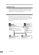
INTRODUCTION Thank you for purchasing the Canon DR-5010C scanner. Please read this manual thoroughly before using the machine to familiarize yourself with it's capabilities, and to make the most of its many functions. After reading this manual, store it in a safe place for future reference. Manuals for the Scanner The DR-5010C scanner has a Startup Manual (this manual) and online help.
Conventions This manual uses the following symbols and indications. Before you start reading this manual, read the following and familiarize yourself with their meanings. WARNING Indicates a warning concerning operations that may lead to death or injury to persons if not performed correctly. In order to use the machine safely, always pay attention to these warnings. CAUTION Indicates a caution concerning operations that may lead to injury to persons, or damage to property if not performed correctly.
Contents INTRODUCTION ....................................................................................................... 2 Manuals for the Scanner ................................................................................................ 2 Conventions ................................................................................................................ 3 Before Using the Scanner ...................................................................................... 5 Safe Operation ...
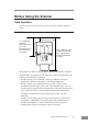
Before Using the Scanner Safe Operation In order to ensure safe operation, be certain to read the cautions described below. Installation Location 17.7" (450 mm) when the Document Feed Tray and Document Feed Tray Extension are closed At least 3.9" (100 mm) when Eject Tray is empty 29.5" (750 mm) when the Document Feed Tray and Document Feed Tray Extension are open The performance of this scanner is affected by the environment in which it is installed.
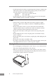
• Avoid locations that are subject to rapid temperature changes. Condensation inside of the scanner can result in inferior image quality. Use this scanner under the following environmental conditions: Temperature: 10˚C to 32.5˚C (50˚F to 90.5˚F) Humidity: 20% to 80% RH • Avoid locating the scanner near equipment that generates electromagnetic fields, including speakers, televisions, and radios. Power • Connect only to a power outlet of the rated voltage and power supply frequency.
Normal Handling WARNING To avoid fire and electric shock, always observe the following warnings when using this scanner. • Do not place flammable chemicals, such as alcohol or paint thinner, near the scanner. • Do not cut, damage, or modify the power cord. Do not place heavy objects on the power cord, do not pull on the power cord, and do not bend the power cord sharply. • Do not plug in or unplug the power cord with wet hands. • Do not use multioutlet adapters to connect multiple devices to one outlet.
CAUTION • Do not set the scanner up on a wobbly platform, a sloped surface, or any other type of unstable location. Do not set up the scanner in a location that is subject to vibration. The scanner could injure someone if it falls or tips over. • Do not block the Ventilation Openings. Doing so could cause the scanner to overheat, creating a risk of fire. • Do not place paper clips, staples, necklaces, or any other metallic objects on top of the scanner.
Features of the DR-5010C The main features of the DR-5010C scanner are listed below. ■ Fast Document Feeding The scanner can scan a maximum of 50 documents per minute in a range of sizes from business cards to 11.6" x 17"/A3 size. (Scanning conditions: Black and white, LTR/A4 size portrait, two sided, 200 dpi) ■ Compact Size The scanner is extremely compact, with measurements of 15.6" x 12.3" x 7.5" (398.4 mm x 312 mm x 191.4 mm) (W x D x H). ■ SCSI III/USB 2.
■ Dropout Color The scanner is equipped with a Dropout Color function that allows you to specify a color for the scanner to omit from scanned images. ■ Skip Blank Page Function The scanner is equipped with a Skip Blank Page function that allows it to scan a document regardless of whether every document is double-sided or single-sided.
Checking the Packing List The contents of the carton in which this scanner is shipped are described below. If anything is missing or damaged, contact your local authorized Canon dealer or service representative. Do Sta rtup cu me nt Sc an ne r Man ua l Re Kee ad this p this ma ma nua nua l tho l in rou a saf ghl e pla y bef ce ore usi for futu ng this re refe sca ren nne ce. r.
Removing the Protective Packing Materials Remove all of the protective packing materials (marked ▼ in the diagrams) before using the scanner. 1. Remove the protective tape from the scanner. 2. Slowly open the Document Feed Tray, then remove the protective tape. Feed tray 3. Hold the edge of the Upper unit as shown in the diagram, and slowly open it until it stops. Upper unit CAUTION The pickup roller is located in the middle of the Upper unit.
4. Remove the protective sheet then the protective material securing the pickup roller. Pickup Roller 5. Remove the roller cover, then remove the protective material securing the retard roller. Replace the roller cover. Roller Cover Retard Roller 6. Gently close the Upper unit. Be sure that the Upper unit is completely closed by pushing on both edges with both hands until you hear a click.
Names and Functions of Parts This section explains the name and function of each part. Familiarize yourself with the parts before connecting the scanner. ■ Front (Feed Tray Open) Document Feed Tray Place the document to be scanned here. (See p. 44.) Document Eject Tray Extension Open if the document extends beyond the edge of the eject tray. (See p. 45.) Document Feed Tray Extension Pull this tray out if the document hangs over the edge of the main tray. (See p. 44.
■ Rear Power Connector Connect to the power cord. (See p. 24.) Document Eject Tray 2 Switch the direction documents are eject by opening or closing this tray. (See p. 46.) Ventilation Openings Interface Ventilation Openings CAUTION Do not block the Ventilation Openings. Doing so could cause the scanner to overheat, creating a risk of fire. ■ Interface DIP Switches Set the SCSI ID. (See p. 22.) Not Used SCSI Connector Connect to a 50-pin half-pitch (pin type) SCSI cable. (See p. 21.
Installing the Scanner Installation Requirements In order to use the DR-5010C, your computer must satisfy the following system requirements: • A computer that meets the following specifications: - CPU: Pentium 4 (1.5 GHz or higher) - Memory: 512 MB or more (1 GB or more recommended) - Hard disk: 1 GB or more available space - CD-ROM drive - SCSI board or Hi-Speed USB 2.0 interface - Monitor: Resolution of 1024 x 768 (XGA) or better recommended • SCSI board or USB 2.
• Use the most recently available SCSI or USB 2.0 driver when using the DR5010C. Contact your local authorized Canon dealer or service representative. for more detailed information. • If the CPU, memory, interface card, and other specifications do not satisfy those recommended, the scanning speed may be greatly reduced and transmission may take a long time. • Even if the computer satisfies the recommended specifications, the scanning speed may be slow depending on the scan settings.
Installation Procedure The procedure for installing the scanner is outlined below. (For a detailed outline of this procedure, see “Connecting the Scanner to Your PC,” on p. 21.) 1. Check the interface card in your computer. (See “Interface Cards,” on p. 19.) 2. Connect the scanner to the PC. (See “Connecting the Scanner to Your PC,” on p. 21.) 3. Connect the power cord to the scanner. (See “Connecting the Power Cord,” on p. 24.) 4. Turn the scanner ON first, and then boot up the PC.
Interface Cards To connect the scanner with a SCSI connection, make sure that the SCSI card is one of the recommended cards listed below that supports SCSI III. SCSI Cards When connecting the scanner via SCSI, verify that the SCSI card you are using is one recommended for use with the scanner.
IMPORTANT • Follow the instructions in your computer's and the USB 2.0 interface card's manuals to install the USB 2.0 interface card into your computer. • Use the most recent version of the USB 2.0 driver provided by Microsoft. Note If the USB 2.0 interface is not compatible with Hi-Speed USB 2.0, scanning speed is reduced.
Connecting the Scanner to Your PC There are two ways of connecting the scanner to your computer, via SCSI or USB. Choose whichever format is suitable for the environment in which you are using your PC. IMPORTANT • When the application is running, do not turn the scanner OFF or unplug the interface cable. • Do not connect both a SCSI cable and a USB cable concurrently. • Do not connect multiple DR-5010C scanners to one (1) computer.
Note • The SCSI ID is set to 2 at the factory. • The SCSI ID is set with the Dip Switches on the back of the scanner. The Dip Switches are on when they are down, and off when they are up. • To change the SCSI ID, be sure to turn OFF the scanner and the computer and refer to the following table to set the SCSI ID.
Connecting USB Interface USB Interface Connection • Be sure to use the USB cable bundled with the scanner or a Hi-Speed USB 2.0compatible cable. • When using a USB extension card that supports Hi-Speed USB 2.0, be sure to choose one verified for use with the scanner. (See “USB 2.0 Interface Card,” on p. 19.) Computer DR-5010C USB Cable IMPORTANT • If the operating system you are using is Windows NT, the connection via USB is not supported.
Connecting the Power Cord Connect the power cord that is provided with this scanner to the power cord connector located on the rear of the scanner, and then plug the cord into a power outlet. WARNING • Be sure to use the power cord provided with the scanner. • Be sure the scanner is turned OFF before connecting the power cord.
Turning the Power ON/OFF Follow the procedures described below when turning the power ON or OFF. Turning the Power ON 1. Turn ON the scanner. The Power Switch is on the lower left of the front of the scanner. Push the Power Switch to turn ON the scanner. The power lamp lights green when the power is ON. ON 2. Turn ON the PC.
• If you are using Windows 98SE, the [Add New Hardware Wizard] dialog box appears. 1. Click the [Next] button. 2. Select [Search for the best driver for your device. (Recommended)], and then click the [Next] button. 3. Insert the setup disc into the computer’s CD-ROM drive. 4. Select [Specify a location], enter “D:\INF” (assuming that “D” is the letter assigned to your CD-ROM drive), and then click the [Next] button. 5. Click the [Next] button. 6. Click the [Finish] button.
3. Select [Search for the best driver in these locations], and then clear the [Search removable media (floppy, CD-ROM...)] check box. Select [Include this location in the search], enter “D:\INF” (assuming that “D” is the letter assigned to your CD-ROM drive), and then click the [Next] button. 4. Although a message appears indicating that the driver “has not passed Windows logo testing”, click the [Continue Anyway] button in the [Hardware Installation] dialog box. 5.
Installing the Software IMPORTANT Before installing the software, be sure to open and read the Readme.txt file on the setup disc. The setup disc included with the scanner contains the following software: • ISIS/TWAIN Driver This driver allows this scanner to be used with ISIScompatible application software or TWAINcompatible application software. The driver must be installed to be able to use the scanner. • CapturePerfect CapturePerfect is software for scanning images that is ISIS compatible.
3. Click the [Start] button, and then select [Run]. The [Run] dialog box appears. 4. In the Open box, enter “D:\Driver\Setup.exe” (assuming that “D” is the letter assigned to your CD-ROM drive), and then click the [OK] button. The Installer starts. 5. Follow the instructions on the screen and complete the installation. 6. Restart Windows when you have completed the installation.
Canon DR-5010C Help Online help for ISIS/TWAIN driver. (See “Using the ISIS/TWAIN Driver,” on p. 35.) PATCH x(xx) (Patch Code Sample Sheet) These sheets are used to automatically separate batches of documents when the scanner recognizes the patch code pattern. (See “Using Patch Code Sheets,” on p. 55.) To use the patch code sheets, you need to install CapturePerfect, which is provided with the scanner, or an application that can handle PDF format files.
Installing CapturePerfect Follow the procedure described below to install CapturePerfect. 1. Turn ON your PC. Windows starts. IMPORTANT If you are using Windows NT 4.0 Workstation, Windows 2000 Professional, or Windows XP, be sure to log on as a user with administrator privileges. 2. Insert the setup disc in the PC’s CD-ROM drive. 3. Click the [Start] button, and then select [Run]. The [Run] dialog box appears. 4. In the Open box, enter “D:\CapturePerfect\Setup.
Uninstalling Software Follow the procedure described below to uninstall the ISIS/TWAIN driver and CapturePerfect. IMPORTANT If you are using Windows NT 4.0 Workstation, Windows 2000 Professional, or Windows XP, be sure to log on as a user with administrator privileges. 1. Click the [Start] button, point to [Settings], and then click [Control Panel]. Note If you are using Windows XP, on the Start menu, click [Control Panel]. The [Control Panel] window is displayed. 2.
The [Add/Remove Programs Properties] dialog box is displayed. Note If you are using Windows XP, the [Add or Remove Programs] dialog box is displayed. 3. Select [Canon DR-5010C Driver] or [CapturePerfect] from the list in the dialog box, and then click [Add/Remove]. Note If you are using Windows XP, click the [Change/Remove] button.
4. The [Confirm File Deletion] dialog box appears. When [Canon DR-5010C Driver] is selected. When [CapturePerfect] is selected 5. Click the [Yes] button to start the uninstaller. Follow the instructions on the screen to finish uninstalling the software.
Using the Software Note • This section provides only the basic procedures for using installed software. Software applications also have their own help. See the applicable help for details about using each software application. • For information about the bundled Adobe Acrobat, see Adobe Acrobat help. Using the ISIS/TWAIN Driver The ISIS/TWAIN driver help describes how to use the ISIS/TWAIN driver.
Using CapturePerfect Follow the procedure described below to start and close CapturePerfect. Note The basic method for scanning using CapturePerfect is described in CapturePerfect help. From the [Help] menu on the CapturePerfect menu bar, click [Help], then refer to the explanation of how to use CapturePerfect. Starting CapturePerfect 1. Turn ON the scanner. 2. Turn ON your computer. Windows starts. 3.
CapturePerfect starts. 4. On the Scan menu, click [Select Scanner]. 5. Select [Canon DR-5010C], and then click the [OK] button. Note If [Canon DR-5010C] is not displayed in the list of scanners, re-install the ISIS/TWAIN driver. (See “Installing the ISIS/TWAIN Driver” on p. 28.
6. On the Scan menu, click [Scanner Setting] and then configure scanning parameters. Note For details about how to configure scanning parameters, see ISIS/TWAIN driver help. (See p. 35.) 7. Execute the scan operation from the [Scan] menu. Note Details about actually using CapturePerfect can be found in CapturePerfect help. To view information about using CapturePerfect, click [Help] on the menu bar. 8. After scanning is complete, select [Exit] on the [File] menu to quit CapturePerfect.
Starting CapturePerfect with the Event Function DR-5010C and CapturePerfect support Windows Scanner Event function. By installing the ISIS/TWAIN driver and CapturePerfect, CapturePerfect starts automatically when the scanners Start Button is pressed. Note Windows NT does not support this function. Confirming Scanner Event 1. Double-click the [Scanners and Cameras] icon. Note • [Scanners and cameras] is not displayed on Windows NT.
2. Select [Canon DR-5010C SCSI] (or [Canon DR-5010C USB]), and then click the [Properties] buton to display Properties. 3. Click the [Events] tab.
4. Make sure that [CapturePerfect] is checked. Note • When an application is started by an event, it may not work correctly depending on the application. • To disable the Event function, check the [Disable device events] check box. • Restart Windows to enable new settings after changing the event settings.
Using the Scanner Documents This scanner can scan documents ranging in size from business cards and checks to 11.6" x 17"/A3 size documents. The size of documents that can be scanned is shown below. Eject Direction (*1) Width Length Weight (*2) Feeding documents are separated Feeding documents are not separated Business cards U-Turn Path 2.08" to 11.8" (53 mm to 300 mm) 2.75" to 17" (70 mm to 432 mm) Straight Path 2.08" to 11.8" (53 mm to 300 mm) 2.
• Scanning documents that are written in pencil or similar material can make the rollers dirty, which can then transfer the dirt to subsequent documents. Always clean the rollers after scanning a document written in pencil. • When scanning a two-sided document that is printed on thin paper, the image on the opposite side of each page may show through. Adjust the scanning intensity in the application software before scanning the document.
Setting Up the Document Feed Tray and the Document Eject Tray 1. Hold the middle of the Document Feed Tray and slowly open it toward you. CAUTION Do not place anything other than documents on the Document Feed Tray. Doing so may damage the scanner, reduce scanning quality, or cause the feed tray to fall off and injure someone. 2. Pull out the Document Feed Tray Extension when scanning large documents.
Document Eject Tray The scanner has two eject methods; documents can be eject to the front of the scanner in a U-Turn Path, or to the back of the scanner in a Straight Path. The eject method can be switched by opening or closing Document Eject Tray 2. Select the eject method according to what you need to do. Document Eject Tray 1 U-Turn Path Straight Path Document Eject Tray 2 Note The Straight Path can be used to scan thick paper, thin paper, and business cards. Using the U-Turn Path 1.
Using the Straight Path 1. Open Document Eject Tray 2. Note When using the Straight Path, the ejected documents are stacked in reverse order to how they were fed. IMPORTANT • Be sure there is enough space for documents that are ejected behind the scanner when using the Straight Path. If there is not enough space for ejected documents, the documents may be damaged or a paper jam may occur. • Open or close Document Eject Tray 2 before starting to scan documents.
Installing the Document Eject Guide When scanning a document that is particularly thin or particularly long, it could droop down over the edge of the Document Eject Tray Extension and become jammed in the scanner. Avoid this problem by attaching the Document Eject Guide. 1. Open the Document Eject Tray Extention toward you. 2. Attach the Document Eject Guide in the order ➀, ➁ as shown. 3. Press the Document Eject Guide to attach it to Document Eject Tray Extention.
4. To remove the Document Eject Guide, lift the Document Eject Tray Extension a little and unhook the Document Eject Guide. 5. Reverse the procedure for attaching the Document Eject Guide to remove it.
Placing a Document for Scanning There are two methods for paper separation, called the Page Separation mode and Bypass mode for feeding documents. Feeding documents continuously from a stack of documents placed in the feed tray is called the Page Separation mode. Feeding documents one sheet at a time by hand or feeding multiple sheet documents, such as invoices that are attached at one end, is called the Bypass mode. The document feed method can be switched by moving the Feed Selection Lever.
2. Straighten the edges of the document to be scanned. CAUTION • Do not place the documents on top of the scanner to align them. Doing so may cause a malfunction. • Be careful when placing a document in the scanner. It is possible to cut your hand on the edge of a sheet of paper. 3. Set the Document Guides so they are wider than the document to be scanned. 4. Place the documents face up into the Document Feed Tray and so they touch the stoppers.
IMPORTANT There is a load limit mark ( ) on the Document Guides. Do not stack documents higher than this mark (approximately 100 sheets of normal copy paper of 20 lb bond (80g/m2)). Doing so may cause a paper jam. 5. Adjust the document guides so they matche the width of the document. Note Before starting a scan, make sure that the document is loaded in the scanner correctly. Scanning a curled document or a creased document can damage the document. 6. Start scanning from the application.
How to Feed with the Bypass Mode 1. Move the Feed Selection Lever on the lower left side of the front of the scanner down ( ). Document Stopper Note • Lowering the Feed Selection Lever causes the Document Stoppers to go down. • The ISIS/TWAIN Driver settings change to the manual feed mode automatically when the Feed Selection Lever is lowered. 2. Place the document into the Document Feed Tray one sheet at a time and adjust the position of the Document Guides. 3. Start scanning from the application. 4.
IMPORTANT • When scanning documents that are fastened together, such as invoices, set the edge that is fastened together as the leading edge. • Note that when scanning with nonseparated feed, if you place several documents that are not fastened together on the feed tray at one time, they will be fed together. • Particularly, very thin or curled documents will not be fed very well. In this case, lightly press on the leading edge of the documents when you set them.
Patch Code Sheets Patch code sheets are sheets printed with a special pattern that is used for separating files without interrupting scanning. When a patch code sheet is read in the scanner and the pattern on the sheet is recognized, the sheet functions as a patch code sheet which allows files to be separated. Note • This section briefly describes how to use the patch code sheets. For details, refer to the ISIS/TWAIN Driver Help.
Functions of Patch Code Sheets • Patch Code Patterns PATCH T (FILE A) When this sheet is detected, the document following this sheet is saved to a separate file. PATCH II (FILE B) When this sheet is detected, the file is separated after this sheet. Note, however, that the setting is ignored, and this sheet is recorded as an image even if the recording of the sheets as an image has been disabled in the patch code detection settings. Using Patch Code Sheets 1. Print out the patch code sheets on a printer.
Effective Area for Detecting Patch Code Patterns 0.2" (5 mm) Patch Code Pattern (Effective area for detecting patch code patterns.) 0.2" (5 mm) 0.2" (5 mm) 3.7" (94 mm) IMPORTANT • When you copy the originals, adjust the size and density settings to match the originals. Extremely dark or light copies may not scan correctly. • When you copy the originals, adjust them so that the patch code pattern is in the effective area for detecting patch code patterns.
Clearing a Paper Jam When paper jams occur during scanning, use the following procedure to clear them. CAUTION Be careful when removing jammed paper. It is possible to cut your hand on the edge of a sheet of paper. 1. Remove any documents that have been left in the eject tray. 2. Close the Document Eject Tray Extention. 3. Hold the Upper unit as shown in the diagram, and open it to the point where you can remove the jammed document. CAUTION The pickup roller is located in the middle of the Upper unit.
4. Remove the jammed document. When the jam occurred in the feed section When the jam occurred in the eject section IMPORTANT Do not pull hard on the jammed sheet; remove it gently. If the sheet does rip, be sure to remove all of the remaining pieces of paper. 5. Close the Upper unit slowly. Be sure that the Upper unit is completely closed by pushing on both edges with both hands until you hear a click.
IMPORTANT Do not force the Upper unit to close. Doing so may damage the scanner. Note After removing the jammed paper, check to see if the last page was scanned, and then continue scanning.
Other Functions The scanner is equipped with a function that stops the scanner when it detects documents that are not fed correctly. Double Feed Detection Function The scanner is equipped with a Double Feed Detection function that automatically detects when two or more documents are fed at the same time (double feed) while doing continuous scanning. There are two methods for multiple feed detection as shown below, the detection method is selected by the ISIS/TWAIN driver.
Regular Maintenance Clean the scanner on a regular basis as described below to maintain peak scanning quality. CAUTION • When cleaning the scanner or inside of the scanner, turn OFF the Power Switch and unplug the power cord from the outlet. • The power needs to be ON when cleaning the rollers and the shading boards. Be careful of electric shocks when working on the scanner while the power is ON.
Cleaning the Sensor Glass and the Rollers If scanned images have extraneous marks, or if the scanned documents are dirty, then the sensor glass or rollers inside the scanner may be dirty. Clean them periodically. 1. Hold the Upper unit as shown in the diagram, and open it slowly until it stops. CAUTION The pickup roller is located in the middle of the Upper unit. Do not hold the protrusion on the Upper unit when you open it. Doing so may deform the pickup roller or cause a feeding error.
2. Use a clean, dry cloth to wipe dirt off the sensor glass. Wipe both the top and bottom sensor glasses. CAUTION Do not use spray type cleaners to clean the scanner. Precision mechanisms, such as the light source, may get wet which will cause a malfunction. IMPORTANT Scratches on the sensor glass may cause marks on the images and could cause feeding errors. If there are scratches on the sensor glass, contact your local authorized Canon dealer or service representative to replace the sensor glass. 3.
IMPORTANT • If you cannot freely rotate the rollers, do not force them to rotate. Just clean the part that you can see. Forcing the rollers to rotate may cause a feeding error. • Be careful not to bend the guide boards that are against the rollers on the Upper unit. 4. Remove the pickup roller, feed roller, and retard roller. (See “Removing and Attaching the Rollers,” on p. 67.) 5. Wipe the removed rollers with a firmly wrung cloth moistened with water.
Cleaning the Shading Boards The shading boards are the white standard boards located behind the platen rollers. A dirty shading board may alter scanned colors or cause marks on the images. 1. Turn ON the power. 2. Hold the Upper unit as shown in the diagram, and open it slowly until it stops. CAUTION The pickup roller is located in the middle of the Upper unit. Do not hold the protrusion on the Upper unit when you open it. Doing so may deform the pickup roller or cause a feeding error.
4. Wipe the only surface of the shading boards with a firmly wrung cloth moistened with water. Do not wipe the back side of the shading boards. Be careful not to bend the shading boards while doing this. CAUTION Wipe both the upper and lower shading boards. Do not spray water or detergent directly on the shading boards. Precision mechanisms, such as the light source, may be damaged. 5. Press the stop button. The shading board goes back in. 6. Close the Upper unit slowly.
Removing and Attaching the Rollers Follow the relevant procedure to remove and attach the pickup roller, feed roller, and retard roller when you clean them or replace them. IMPORTANT Feed rollers are consumable parts. When the rollers start to wear out, paper jams and misfeeds may occur more often. When this happens, buy a exchange roller kit, and replace the pickup roller, feed roller, and the retard roller. CAUTION • Turn ON the power to the scanner to remove or attach the pickup roller.
• Contact your local authorized Canon dealer or service representative for information about the exchange roller kit (pickup roller, retard roller, and feed roller). Resetting the Counter After replacing the feed rollers, reset the counter according to the following procedure. 1. Click the [Start] button, point to [Settings], and then click [Control Panel]. Note If you are using windows XP, on the Start menu, click [Control Panel]. The [Control Panel] window is displayed. 2.
3. Click on [Properties] for the scanner you are using. 4. Click the [Counter] tab. 5. Press the [Reset] button, and then make sure that the counter for the Roller being used is set to 0.
Removing and Attaching the Pickup Roller Follow the procedures below to remove and attach the pickup roller for cleaning or replacement. CAUTION • Turn ON the power to the scanner to remove or attach the pickup roller. Be careful when working on the scanner when the power is ON. • Do not use excessive force when removing or attaching the rollers. Doing so may damage them. Removing the Pickup Roller 1. Turn ON the power.
CAUTION The pickup roller is located in the middle of the Upper unit. Do not hold the protrusion on the Upper unit when you open it. Doing so may deform the pickup roller or cause a feeding error. 3. Push up on the pickup roller to open the hook, and then remove the pickup roller. Attaching the Pickup Roller 1. Hold the new pickup roller (or the one you removed) by both sides of its shaft, and place it on the hooks. IMPORTANT Take note of the orientation of the pickup roller.
2. Place the shaft of the pickup roller on the hooks, and then press it into place. 3. Make sure that the shaft of the pickup roller is correctly inserted. 4. Close the Upper unit slowly. Be sure that the Upper unit is completely closed by pushing on both edges with both hands until you hear a click. IMPORTANT Do not force the Upper unit to close. Doing so may damage the scanner.
Removing and Attaching the Feed Roller Follow the procedure below to remove and attach the feed roller unit for cleaning or replacement. CAUTION Do not use excessive force when removing or attaching the rollers. Doing so may damage them. Removing the Feed Roller 1. Hold the Upper unit as shown in the diagram, and open it slowly until it stops. CAUTION The pickup roller is located in the middle of the Upper unit. Do not hold the protrusion on the Upper unit when you lift it up.
3. Move the roller lock lever down and forward (➀), and then slide it to the right (➁). 4. Shift the feed roller to the right to remove it. Attaching the Feed Roller 1. Position the feed roller so the notch in the roller is facing the scanner's shaft.
2. Slide the roller lock lever to the left, and insert it into the feed roller hole. 3. Lift up the roller lock lever and lock the feed roller. 4. Attach the roller cover.
5. Close the Upper unit slowly. Be sure that the Upper unit is completely closed by pushing on both edges with both hands until you hear a click. IMPORTANT Do not force the Upper unit to close. Doing so may damage the scanner.
Removing and Attaching the Retard Roller Follow the procedure below to remove and attach the retard roller when you clean or replace it. CAUTION Do not use excessive force when removing or attaching the rollers. Doing so may damage them. Removing the Retard Roller 1. Hold the Upper unit as shown in the diagram, and open it slowly until it stops. CAUTION The pickup roller is located in the middle of the Upper unit. Do not hold the protrusion on the Upper unit when you open it.
3. Move the roller lock lever upward (➀), and then slide it to the right (➁). 4. Shift the retard roller to the right to remove it. Attaching the Retard Roller 1. Position the retard roller so the notch in the roller is facing the scanner's shaft.
2. Slide the roller lock lever to the left, and insert it into the retard roller hole. 3. Move the roller lock lever forward and down to lock the retard roller. 4. Attach the roller cover.
5. Close the Upper unit slowly. Be sure that the Upper unit is completely closed by pushing on both edges with both hands until you hear a click. IMPORTANT Do not force the Upper unit to close. Doing so may damage the scanner.
Troubleshooting This section describes common problems that may occur while you are using the scanner, and how to resolve them. Refer to the troubleshooting section related to the problem that you have encountered. The Scanner Does Not Turn ON ................................................. p. 81 The PC Does Not Recognize the Scanner ................................. p. 82 (Connecting via SCSI) The PC Does Not Recognize the Scanner ................................. p. 84 (Connecting via USB 2.
The PC Does Not Recognize the Scanner (Connecting via SCSI) The following are possible causes of the PC failing to recognize the scanner. Check each possible cause. Cause The scanner is not connected correctly. Remedy Make sure that the scanner and the computer are correctly connected. (See p. 21.) Cause The SCSI card is not correctly installed in the PC. Remedy Refer to the manual for the SCSI card and the computer and install the SCSI card to the computer correctly.
Cause The scanner’s SCSI ID is identical to the SCSI ID of another device. Remedy Check the SCSI IDs of all SCSI devices connected to the system and set a unique SCSI ID for the scanner. (See p. 22.) Cause The terminator is not set correctly. Remedy Shut down both the PC and the scanner, and then turn the scanner ON first, and then the PC. (See p. 25.) Cause There is a problem with another SCSI device that is connected in the daisy chain.
The PC Does Not Recognize the Scanner (Connecting via USB 2.0) The following are possible causes of the PC failing to recognize the scanner. Check each possible cause. 84 Cause The scanner is not connected correctly. Remedy Check the USB cable connections between the scanner and the PC. (See “Connecting USB Interface,” on p. 23.) Cause The USB 2.0 interface card is not inserted in the PC correctly. Remedy Reseat the USB 2.
Scanning Is Slow (Connecting via USB 2.0) The following problems might cause the scanner to be slow. Try the solutions according to the problem. Cause The USB 2.0 interface card does not support Hi-Speed 2.0. Remedy Use the recommended USB 2.0 interface card. (See p. 19.) Cause The USB 2.0 interface cable does not support Hi-Speed 2.0. Remedy Use the USB cable provided with the scanner. (See p. 23.) Cause The USB HUB does not support Hi-Speed 2.0.
Resulting Scanned Images Are Not Correct If the resulting scanned images are not crisp, if there are lines or spots on the images, or if there is some other problem with scanned images, likely causes are listed below. Check each item and take the appropriate action. Cause The sensor glass or the rollers inside the scanner are dirty. Remedy Clean the sensor glass and rollers as described on p. 62. Cause The scanners internal platen glass is scratched.
Specifications Type Sheet through image scanner Scanning Document Specifications Width: 2.08" to 11.8" (53 to 300 mm) Length: 2.75" to 17" (70 to 432 mm) Weight: Using the U-Turn Path (separated documents) 14 to 32 lb bond (0.0024" to 0.0059") 52 to 128 g/m2 (0.06 mm to 0.15 mm) (nonseparated documents) 11 to 40 lb bond (0.0020" to 0.0079") 42 to 157 g/m2 (0.05 mm to 0.2 mm) Weight: Using the Straight Path (separated documents) 14 to 32 lb bond (0.0024" to 0.0059") 52 to 128 g/m2 (0.06 mm to 0.
24-bit Color Simplex 200 x 200 dpi 300 x 300 dpi 600 x 600 dpi Duplex 200 x 200 dpi 300 x 300 dpi 600 x 600 dpi 50 pages/minute 40 pages/minute 6 pages/minute 100 images/minute 70 images/minute 16 images/minute Amount of paper that can be stacked in automatic feeder 10 mm stack, maximum (100 sheets of 20 lb bond (80 g/m2)) Interface SCSI-III / Hi-Speed USB 2.0 Other Functions Double feed detection, skew detection Dimensions (with trays closed) 15.6" x 12.3" x 7.5" (W x D x H) 398.
External Dimensions 15.6" (398.4) Units: inches (units in parentheses are millimeters) 26.3" (668) (Document Feed Tray Extension is open) 21.3" (541) (Document Feed Tray is open) 17.3" (440) (Document Eject Tray 2 is open) 7.5" (191.4) 3.2" (82) 5.6" (142) 7.4" (188) 7.6" (194) (Document Eject Guide is open) 3.7" (95) 12.
Index C CapturePerfect Event Function ..................................... 39 Install .................................................... 31 Uninstall ............................................... 32 Using .................................................... 36 Cleaning Glass ..................................................... 62 Inside .................................................... 61 Rollers .................................................. 62 Scanner .........................................
MEMO
MEMO
FCC REGULATIONS (For 120 V model) Document Scanner, Model M11051 This device complies with Part 15 of the FCC Rules. Operation is subject to the following two conditions: (1) This device may not cause harmful interference, and (2) this device must accept any interference received, including interference that may cause undesired operation. Note: This equipment has been tested and found to comply with the limits for a Class B digital device, pursuant to Part 15 of the FCC Rules.
CANON ELECTRONICS INC. 1248, SHIMOKAGEMORI, CHICHIBU-SHI, SAITAMA 369-1892, JAPAN CANON U.S.A. INC. ONE CANON PLAZA, LAKE SUCCESS, N.Y. 11042, U.S.A. CANON CANADA INC. 6390 DIXIE ROAD, MISSISSAUGA, ONTARIO L5T 1P7, CANADA CANON EUROPA N.V. BOVENKERKERWEG 59-61, P.O.BOX 2262, 1180 EG AMSTELVEEN, THE NETHERLANDS CANON LATIN AMERICA, INC. 703 WATERFORD WAY, SUITE 400 MIAMI, FLORIDA 33126, U.S.A. CANON AUSTRALIA PTY. LTD. 1 THOMAS HOLT DRIVE, NORTH RYDE, SYDNEY. N.S.W, 2113. AUSTRALIA CANON SINGAPORE PTE. LTD.