
Instructions


- 2 -
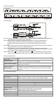
I/O Terminal Layout
L-L+FGL-L+
DVP04PT-S
FGI- L+FGI-L-L+ FGI-L-I-
CH1 Ch2 Ch3 Ch4
[ Figure 2 ]
L-L+L-L+
DVP06PT
I- L+I-L-L+ I-L-I-
CH1
L-L+ I- L+ I-L-
CH2
CH3 CH4 CH5 CH6
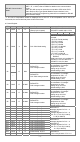
External Wiring
*2
,
AG
Shielded cable* 1
AG
CH1
2-Wire
CH6
3-Wire
L+
L-
I-
Pt1000
Pt100
L+
L-
I-
*2
Shielded cable*1
Note1: Use only the wires that are packed with the temperature sensor for analog input and separate from
other power line or any wire that may cause noise.
Note2: 3-wire RTD sensor provides a compensation loop that can be used to subtract the wire
resistance while 2-wire RTD sensor has no mechanism to compensate. Use cables
(3-wired) with the same length (less than 200 m) and wire resistance of less than 20
ohm.
Note3: If there is noise, please connect the shielded cables to the system earth point, and then ground the
system earth point or connect it to the distribution box.
Note4: Please keep wires as short as possible when connecting the module to a device whose
temperature is going to be measured, and keep the power cable used as far away from the cable
connected to a load as possible to prevent noise interference.
Note5: Please connect
on a power supply module and on the temperature module to a system
ground, and then ground the system ground or connect the system ground to a distribution box.
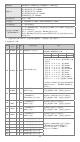
Electrical Specifications
Max. rated power
consumption
2W
Operation/storage
Operation: 0°C~55°C (temp.), 5~95% (humidity), pollution degree 2
Storage: -25°C~70°C (temp.), 5~95% (humidity)
Vibration/shock resistance
International standards: IEC61131-2, IEC 68-2-6 (TEST Fc)/ IEC61131-2
& IEC 68-2-27 (TEST Ea)
Series connection to
DVP-PLC MPU
The modules are numbered from 0 to 7 automatically by their distance
from MPU. No.0 is the closest to MPU and No.7 is the furthest. Maximum
8 modules are allowed to connect to MPU and will not occupy any digital
I/O points.
Functional Specifications
DVP04/06PT-S Celsius (°C) Fahrenheit (°F)
Analog input channel 4/6 channels per module
Sensors type
2-wire/3-wire Pt100 / Pt1000 3850 PPM/°C (DIN 43760 JIS C1604-1989)
/ Ni100 / Ni1000 / LG-Ni1000 / Cu100 / Cu50/ 0~300Ω/ 0~3000Ω
Current excitation 1.53mA / 204.8uA
Temperature input range Please refer to the temperature/digital value characteristic curve.
Digital conversion range Please refer to the temperature/digital value characteristic curve.
Resolution 0.1°C 0.18°F
Overall accuracy
0.6% of full scale during 0 ~ 55°C (32 ~ 131°F)
Response time DVP04PT-S: 200ms/channel; DVP06PT-S: 160/ms/channel
Isolation method
(between digital and analog
circuitry)
There is no isolation between channels.
500VDC between digital/analog circuits and Ground
500VDC between analog circuits and digital circuits
500VDC between 24VDC and Ground
Digital data format 2’s complement of 16-bit
Average function Yes (DVP04PT-S: CR#2 ~ CR#5 / DVP06PT-S: CR#2)
Self diagnostic function Every channel has the upper/lower limit detection function.