
Instructions


- 4 -
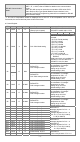
CR# Address Latched Attribute Register content Description
#20 H’4078 X R Present temp. of CH3
DVP06PT-S:
Present temperature of CH1~6
Unit: 0.1°C, 0.01 Ω (0~300 Ω),
0.1 Ω (0~3000 Ω)
#21 H’4079 X R Present temp. of CH4
#22 -- X R Present temp. of CH5
#23 -- X R Present temp. of CH6
#24 H’407C X R Present temp. of CH1
DVP04PT-S:
Present temperature of CH 1~4
DVP06PT-S:
Present temperature of CH 1~6
Unit: 0.1°C, 0.01 Ω (0~300 Ω),
0.1 Ω (0~3000 Ω)
#25 H’407D X R Present temp. of CH2
#26 H’407E X R Present temp. of CH3
#27 H’407F X R Present temp. of CH4
#28 -- X R Present temp. of CH5
#29 -- X R Present temp. of CH6
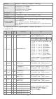
#29 H’4081 X R/W
DVP04PT-S:
PID mode setup
Set H’5678 as PID mode and other
values as normal mode
Default value is H’0000.
#30 H’4082 X R Error status
Data register stores the error
status. Refer to the error code chart
for details.
#31
H’4083 O R/W
DVP04PT-S:
Communication address
setup
Set up the RS-485 communication
address; setting range: 01~254.
Default: K1
-- X R/W
DVP06PT-S:
CH5~CH6 Mode setting
CH5 mode: b0 ~ b3
CH6 mode: b4 ~ b7
See CR#1 for reference
32
H’4084 O R/W
DVP04PT-S:
Communication format
setting
For baud rate, the settings are
4,800/9,600/19,200/38,400/57,600/
115,200 bps.
Communication format:
ASCII: 7,E,1 / 7,O,1 / 8,E,1 / 8,O,1 /
8,N,1
RTU: 8,E,1 / 8,O,1 / 8,N,1
Factory default : ASCII,9600,7,E,1
(CR#32=H’0002)
Refer to ※CR#32 communication
format settings at the end of this
table for more information.
-- X R/W
DVP06PT-S:
CH5~CH6
Error LED indicator setting
b15~12 b11~9 b8~6 b5~3 b2~0
ERR
LED
reserved CH6 CH5
b12~13 correspond to CH5~6,
when bit is ON, the scale exceeds
the range, and the Error LED
indicator flashes.
#33
H’4085 O R/W
DVP04PT-S:
CH1~CH4
Reset to default setting
And Error LED indicator
setting
b15~12 b11~9 b8~6 b5~3 b2~0
ERR
LED
CH4 CH3 CH2 CH1
If b2~b0 are set to 100, all the
setting values of CH1 will be reset
to the defaults. To reset all
channels to defaults, set b11~0 to
H’924 (DVP04PT-S supports single
and all channels reset; DVP06PT-S
supports all channels reset only).
b12~15 correspond to CH1~4,
when bit is ON, the scale exceeds
the range, and the Error LED
indicator flashes.
-- X R/W
DVP06PT-S:
CH1~CH4 Reset to default
setting And CH1~CH4 Error
LED indicator setting
#34 H’4086 O R Firmware version
Display version in hexadecimal. ex:
H’010A = version 1.0A
#35 ~ #48 For system use
Symbols: O means latched. (Supported with RS485, but does not support when connecting to MPUs.)
X means not latched. R means can read data by using FROM instruction or RS-485.
W means can write data by using TO instruction or RS-485.
1. Added the RESET function is only for 04PT-S modules with firmware V4.16 or later and not available
for 06PT-S. Connect the module power input to 24 VDC and write H’4352 into CR#0 and then turn the
power off and on again; all parameters in modules, including communication parameters are restored
to factory defaults.
2. If you want to use Modbus address in decimal format, you can transfer a hexadecimal register to
decimal format and then add one to have it become a decimal Modbus register address. For example
transferring the address “H’4064” of CR#0 in hexadecimal format to decimal format, to have the result
16484 and then adding one to it, you have 16485, the Modbus address in decimal format.